Engineering Mechanics: Dynamics (14th Edition)
14th Edition
ISBN: 9780133915389
Author: Russell C. Hibbeler
Publisher: PEARSON
expand_more
expand_more
format_list_bulleted
Concept explainers
Videos
Textbook Question
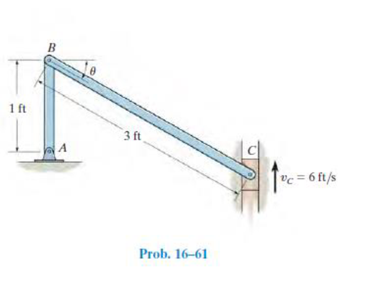
Chapter 16.5, Problem 61P
Also, sketch the position of link BC when θ = 55°, 45°, and 30° to show its general plane motion.
Expert Solution & Answer

Trending nowThis is a popular solution!

Students have asked these similar questions
Please do not use any AI tools to solve this question.
I need a fully manual, step-by-step solution with clear explanations, as if it were done by a human tutor.
No AI-generated responses, please.
Please do not use any AI tools to solve this question.
I need a fully manual, step-by-step solution with clear explanations, as if it were done by a human tutor.
No AI-generated responses, please.
[Q2]: The cost information supplied by the cost accountant is as follows:Sales 20,00 units, $ 10 per unitCalculate the (a/ newsale guantity and (b) new selling price to earn the sameVariable cost $ 6 per unit, Fixed Cost $ 30,000, Profit $ 50,000profit ifi) Variable cost increases by $ 2 per unitil) Fixed cost increase by $ 10,000Ili) Variable cost increase by $ 1 per unit and fixed cost reduces by $ 10,000
Chapter 16 Solutions
Engineering Mechanics: Dynamics (14th Edition)
Ch. 16.3 - Determine its constant angular acceleration and...Ch. 16.3 - Determine the angular acceleration when it has...Ch. 16.3 - Determine the time it takes to achieve an angular...Ch. 16.3 - If the angular displacement of the wheel is =...Ch. 16.3 - Determine the magnitude of the velocity and...Ch. 16.3 - Determine the velocity of the cylinder and the...Ch. 16.3 - Determine the magnitudes of the velocity and...Ch. 16.3 - If the disk is originally rotating at 0 = 12...Ch. 16.3 - It it is subjected to a constant angular...Ch. 16.3 - If it is subjected to a constant angular...
Ch. 16.3 - Determine the number of revolutions, the angular...Ch. 16.3 - Determine the number of revolutions it must...Ch. 16.3 - Also, find the number of revolutions of gear D to...Ch. 16.3 - Gears A, B, C, and D have radii of 15 mm, 50 mm,...Ch. 16.3 - Determine the magnitude of acceleration of point B...Ch. 16.3 - pulley A is given a constant angular acceleration...Ch. 16.3 - Starting from rest, determine the angular...Ch. 16.3 - If the engine turns pulley A at A = (20t + 40)...Ch. 16.3 - If the engine turns pulley A at A = 60 rad/s,...Ch. 16.3 - Determine the angular velocity of the disk and its...Ch. 16.3 - Determine the magnitudes of the normal and...Ch. 16.3 - Determine the magnitudes of the normal and...Ch. 16.3 - If this gear is initially turning at A = 15 rad/s,...Ch. 16.3 - If this gear is initially turning at A = 15 rad/s,...Ch. 16.3 - Determine the brushs angular velocity when t = 4...Ch. 16.3 - If this gear is initially turning at (A)0 = 20...Ch. 16.3 - Determine the magnitudes of the velocity and the n...Ch. 16.3 - If the motor turns gear A with an angular...Ch. 16.3 - If the motor turns gear A with an angular...Ch. 16.3 - and the meshed pinion gear B on the propeller...Ch. 16.3 - determine the magnitude of the velocity and...Ch. 16.3 - If the gears A and have the dimensions shown,...Ch. 16.3 - and the meshed pinion gear B on the propeller...Ch. 16.3 - and the meshed pinion gear B on the propeller...Ch. 16.3 - If the canisters are centered 200 mm apart on the...Ch. 16.3 - Determine the largest angular velocity of gear B...Ch. 16.3 - The shaft of the motor M turns with an angular...Ch. 16.3 - If A has a constant angular acceleration of A = 30...Ch. 16.3 - If the angular displacement of A it A = (5t3 +...Ch. 16.3 - This gear is connected to gear B, which is fixed...Ch. 16.3 - Express the result in Cartesian vector form.Ch. 16.3 - Determine the velocity and acceleration of point D...Ch. 16.3 - At the instant shown it is rotating about the y...Ch. 16.3 - Determine the magnitudes of the velocity and...Ch. 16.4 - Determine the angular velocity and angular...Ch. 16.4 - Determine the angular acceleration and angular...Ch. 16.4 - Determine the angular acceleration and angular...Ch. 16.4 - Determine the angular velocity and angular...Ch. 16.4 - Determine the angular velocity of the connecting...Ch. 16.4 - The cam rotates with a constant counterclockwise...Ch. 16.4 - The pin connection at O does not cause an...Ch. 16.4 - Determine the velocity of the follower rod AB as...Ch. 16.4 - The pin connection at O does not cause an...Ch. 16.4 - Determine the velocity and acceleration of the peg...Ch. 16.4 - Determine the velocity and acceleration of block...Ch. 16.4 - Determine the angular velocity and angular...Ch. 16.4 - If the slotted arm is causing A to move downward...Ch. 16.4 - If the wedge moves to the left with a constant...Ch. 16.4 - If the rollers do not slip, determine their...Ch. 16.4 - If no slipping occurs between the disk D and the...Ch. 16.4 - Determine the velocity and acceleration of...Ch. 16.5 - If roller A moves to the right with a constant...Ch. 16.5 - Determine the magnitude of the velocity of point B...Ch. 16.5 - The cable wraps around the inner core, and the...Ch. 16.5 - If crank OA rotates with an angular velocity of =...Ch. 16.5 - If rod AB slides along the horizontal slot with a...Ch. 16.5 - Determine the velocity of the peg at B at this...Ch. 16.5 - Determine the velocity of point B at this instant.Ch. 16.5 - If the block at C is moving downward at 4 ft/s,...Ch. 16.5 - Determine the velocity of block C and the angular...Ch. 16.5 - Determine the angular velocities of links A B and...Ch. 16.5 - Also, sketch the position of link BC when = 55,...Ch. 16.5 - Link BC rotates clockwise with an angular velocity...Ch. 16.5 - If the angular velocity of link AB is AB = 3...Ch. 16.5 - Determine the velocity of the gear rack C.Ch. 16.5 - If B is moving to the right at 8 ft/s and C is...Ch. 16.5 - Determine the angular velocity of the gear and the...Ch. 16.5 - Determine the velocity of point A on the rim of...Ch. 16.5 - Link CB is horizontal at this instant.Ch. 16.5 - Determine the velocity of the slider C at the...Ch. 16.5 - Determine the velocity of block C and the angular...Ch. 16.5 - If AB has an angular velocity AB = 8 rad/s,...Ch. 16.5 - If the slider block A is moving downward at vA = 4...Ch. 16.5 - If the slider block A is moving downward at A = 4...Ch. 16.5 - This gear has an inner hub C which is fixed to B...Ch. 16.5 - If link AB is rotating at AB =3 rad/s, determine...Ch. 16.5 - If link CD is rotating at CD = 5 rad/s, determine...Ch. 16.5 - By locking or releasing certain gears, it has the...Ch. 16.5 - If the ring gear A rotates clockwise with an...Ch. 16.5 - It consists of a driving piston A, three links,...Ch. 16.5 - Because of the rotational motion of lint AB and...Ch. 16.6 - Establish the location of the instantaneous center...Ch. 16.6 - Determine the angular velocity of the rod and the...Ch. 16.6 - Determine the angular velocity of link BC and...Ch. 16.6 - The gear rack B is fixed.Ch. 16.6 - If cable AB is unwound with a speed of 3 m/s, and...Ch. 16.6 - Determine the angular velocity of link BC and the...Ch. 16.6 - Determine the angular velocity of links BC and CD...Ch. 16.6 - Assume the geometry is known.Ch. 16.6 - Determine the angular velocity of link AB at the...Ch. 16.6 - Determine the angular velocity of the link CB at...Ch. 16.6 - Determine the velocities of the cylinders center C...Ch. 16.6 - Determine the velocities of points A and B on the...Ch. 16.6 - Determine the velocities of points A and B.Ch. 16.6 - If rod CD is rotating with an angular velocity CD...Ch. 16.6 - If bar AB has an angular velocity AB = 6 rad/s,...Ch. 16.6 - Under these conditions, what is the speed at A if...Ch. 16.6 - Due to slipping, points A and B on the rim of the...Ch. 16.6 - Determine the velocities of the center point C and...Ch. 16.6 - Determine the velocity of point D and the angular...Ch. 16.6 - Determine the velocity of point P, and the angular...Ch. 16.6 - If connected bar CD is rotating with an angular...Ch. 16.6 - Determine the speeds of points A, B, and C caused...Ch. 16.6 - Determine the velocity of the gear rack C.Ch. 16.6 - If the hub gear H and ring gear R have angular...Ch. 16.6 - What is the angular velocity of the spur gear?Ch. 16.6 - Determine the angular velocity of rod CD at the...Ch. 16.6 - If bar CD is rotating with an angular velocity of...Ch. 16.6 - If the link rotates about the fixed point B at 4...Ch. 16.7 - if the sun gear D is rotating clockwise at D = 5...Ch. 16.7 - The angular velocity is given.Ch. 16.7 - Determine the angular acceleration of the rod and...Ch. 16.7 - Determine the acceleration of point A.Ch. 16.7 - At the instant shown, the center O of the gear...Ch. 16.7 - Determine the angular acceleration of the gear at...Ch. 16.7 - Determine the angular acceleration of link BC at...Ch. 16.7 - Determine the angular acceleration of link BC and...Ch. 16.7 - Determine the velocity sod acceleration of the...Ch. 16.7 - Determine the acceleration of the top of the...Ch. 16.7 - Determine the acceleration of the bottom A of the...Ch. 16.7 - Determine the velocity and acceleration of the...Ch. 16.7 - Determine the velocity and acceleration of the...Ch. 16.7 - At the instant shown, point A has the motion...Ch. 16.7 - Determine the angular velocity and angular...Ch. 16.7 - Determine the angular velocity and angular...Ch. 16.7 - Determine the angular acceleration of link AB and...Ch. 16.7 - Determine the angular acceleration of link CD if...Ch. 16.7 - Determine the velocity and acceleration of point A...Ch. 16.7 - Determine the velocity and acceleration of point B...Ch. 16.7 - If it is pulled with a constant velocity v,...Ch. 16.7 - If it does not slip at A, determine the...Ch. 16.7 - If it does not slip at A, determine the...Ch. 16.7 - As cord CF unwinds from the inner rim of the...Ch. 16.7 - Determine the velocity and acceleration of point B...Ch. 16.7 - Determine the angular velocity and angular...Ch. 16.7 - If link DE has the angular motion shown, determine...Ch. 16.7 - If member AB has the angular motion shown,...Ch. 16.7 - If member AB has the angular motion shown,...Ch. 16.7 - Determine the acceleration of points A and B on...Ch. 16.7 - At a given instant, A has a velocity of vA = 4...Ch. 16.7 - Determine the angular acceleration of rod AB at...Ch. 16.8 - Determine the acceleration of A at the instant...Ch. 16.8 - If at the same instant the disk has the angular...Ch. 16.8 - At the same instant, the boom is extending with a...Ch. 16.8 - Prob. 131PCh. 16.8 - Prob. 132PCh. 16.8 - Determine the velocity and acceleration of a water...Ch. 16.8 - At the instant shown, the cord is pulled down...Ch. 16.8 - Prob. 135PCh. 16.8 - Determine the velocity and acceleration of point C...Ch. 16.8 - Prob. 137PCh. 16.8 - Determine the magnitudes of the velocity and...Ch. 16.8 - If link AD is rotating at a constant rate of AD =...Ch. 16.8 - Determine the angular velocity and angular...Ch. 16.8 - If rod AB has an angular velocity of 2 rad/s and...Ch. 16.8 - Prob. 142PCh. 16.8 - If the gears center O moves with the velocity and...Ch. 16.8 - Prob. 144PCh. 16.8 - Prob. 145PCh. 16.8 - Also at this instant the car mounted at the end of...Ch. 16.8 - If the slider block C is fixed to the disk that...Ch. 16.8 - Determine the velocity and acceleration of car A...Ch. 16.8 - Determine the velocity and acceleration of car B...Ch. 16.8 - Link AB has a pin at B which is confined to move...Ch. 16.8 - Prob. 151PCh. 16.8 - The star wheel A makes one sixth of a revolution...Ch. 16.8 - If the tires do not slip on the pavement,...Ch. 16.8 - Determine the velocity and deceleration of the...Ch. 16.8 - Determine the speed of block B when it has risen s...Ch. 16.8 - At the instant shown, it has an acceleration of...Ch. 16.8 - If bar AB has an angular velocity AB = 6 rad/s,...Ch. 16.8 - If the cable does not slip on the pulley's...Ch. 16.8 - Determine the acceleration of the pin at C and the...Ch. 16.8 - If it does not slip at A, determine the...Ch. 16.8 - Determine the velocity and acceleration of the...
Knowledge Booster


Learn more about
Need a deep-dive on the concept behind this application? Look no further. Learn more about this topic, mechanical-engineering and related others by exploring similar questions and additional content below.Similar questions
- can you please help me perform Visual Inspection and Fractography of the attatched image: Preliminary examination to identify the fracture origin, suspected fatigue striation, and corrosion evidences.arrow_forwardcan you please help[ me conduct Causal Analysis (FTA) on the scenario attatched: FTA diagram which is a fault tree analysis diagram will be used to gain an overview of the entire path of failure from root cause to the top event (i.e., the swing’s detachment) and to identify interactions between misuse, material decay and inspection errors.arrow_forwardhi can you please help me in finding the stress intensity factor using a k-calcluator for the scenario attathced in the images.arrow_forward
- Hi, can you please help me .Identify and justify suitable analytical techniques of the scenario below, bearing in mind the kinds of information being handled to reach a conclusion (methodology). A child swing set was discovered to have failed at the fixing at the top of the chains connecting the seat to the top of the swing set. A 12 mm threaded steel bolt, connecting the shackle to the top beam, failed at the start of the threaded region on the linkage closest to the outside side of the swing set . The linkage and bolts were made of electro galvanised mild steel . The rigid bar chain alternatives and fixings were of the same material and appeared to be fitted in accordance with guidelines. The yield strength of the steel used is 260 MPa and the UTS is 380 MPa. The bolt that failed was threaded using a standard thread with a pitch (distance between threads) of 1.75 mm and a depth of approximately 1.1 mm. The swing set in question had been assigned to ‘toddlers’ with the application of…arrow_forwardHi, can you please define and calculate the failure mode of the linkage that failed on the swing (images added) : A child swing set was discovered to have failed at the fixing at the top of the chains connecting the seat to the top of the swing set. A 12 mm threaded steel bolt, connecting the shackle to the top beam, failed at the start of the threaded region on the linkage closest to the outside side of the swing set . The linkage and bolts were made of electro galvanised mild steel . The rigid bar chain alternatives and fixings were of the same material and appeared to be fitted in accordance with guidelines. The yield strength of the steel used is 260 MPa and the UTS is 380 MPa. The bolt that failed was threaded using a standard thread with a pitch (distance between threads) of 1.75 mm and a depth of approximately 1.1 mm. The swing set in question had been assigned to ‘toddlers’ with the application of a caged-type seat. However, the location was within the play area not…arrow_forwardPage 11-68. The rectangular plate shown is subjected to a uniaxial stress of 2000 psi. Compute the shear stress and the tensile developed on a plane forming an angle of 30° with the longitud axis of the member. (Hint: Assume a cross-sectional area of unity) 2000 psi 2000 psi hparrow_forward
- 11-70. A shear stress (pure shear) of 5000 psi exists on an element. (a) Determine the maximum tensile and compressive stresses caused in the element due to this shear. (b) Sketch the element showing the planes on which the maximum tensile and compressive stresses act.arrow_forward11-20. An aluminum specimen of circular cross section, 0.50 in. in diameter, ruptured under a tensile load of 12,000 lb. The plane of failure was found to be at 48° with a plane perpendicular to the longitudinal axis of the specimen. (a) Compute the shear stress on the failure plane. (b) Compute the maximum tensile stress. (c) Compute the tensile stress on the failure plane. hparrow_forwardA long flat steel bar 13 mm thick and 120 mm wide has semicircular grooves as shown and carries a tensile load of 50 kN Determine the maximum stress if plate r= 8mm r=21mm r=38mmarrow_forward
- Problem 13: F₁ = A =250 N 30% Determine the moment of each of the three forces about point B. F₂ = 300 N 60° 2 m -3 m B 4 m F3=500 Narrow_forward3 kN 3 kN 1.8 kN/m 80 mm B 300 mm D an 1.5 m-1.5 m--1.5 m- PROBLEM 5.47 Using the method of Sec. 5.2, solve Prob. 5.16 PROBLEM 5.16 For the beam and loading shown, determine the maximum normal stress due to bending on a transverse section at C.arrow_forward300 mm 3 kN 3 kN 450 N-m D E 200 mm 300 mm PROBLEM 5.12 Draw the shear and bending-moment diagrams for the beam and loading shown, and determine the maximum absolute value (a) of the shear, (b) of the bending moment.arrow_forward
arrow_back_ios
SEE MORE QUESTIONS
arrow_forward_ios
Recommended textbooks for you
 Elements Of ElectromagneticsMechanical EngineeringISBN:9780190698614Author:Sadiku, Matthew N. O.Publisher:Oxford University Press
 Mechanics of Materials (10th Edition)Mechanical EngineeringISBN:9780134319650Author:Russell C. HibbelerPublisher:PEARSON
 Thermodynamics: An Engineering ApproachMechanical EngineeringISBN:9781259822674Author:Yunus A. Cengel Dr., Michael A. BolesPublisher:McGraw-Hill Education
 Control Systems EngineeringMechanical EngineeringISBN:9781118170519Author:Norman S. NisePublisher:WILEY
 Mechanics of Materials (MindTap Course List)Mechanical EngineeringISBN:9781337093347Author:Barry J. Goodno, James M. GerePublisher:Cengage Learning
 Engineering Mechanics: StaticsMechanical EngineeringISBN:9781118807330Author:James L. Meriam, L. G. Kraige, J. N. BoltonPublisher:WILEY
Elements Of Electromagnetics
Mechanical Engineering
ISBN:9780190698614
Author:Sadiku, Matthew N. O.
Publisher:Oxford University Press
Mechanics of Materials (10th Edition)
Mechanical Engineering
ISBN:9780134319650
Author:Russell C. Hibbeler
Publisher:PEARSON
Thermodynamics: An Engineering Approach
Mechanical Engineering
ISBN:9781259822674
Author:Yunus A. Cengel Dr., Michael A. Boles
Publisher:McGraw-Hill Education
Control Systems Engineering
Mechanical Engineering
ISBN:9781118170519
Author:Norman S. Nise
Publisher:WILEY
Mechanics of Materials (MindTap Course List)
Mechanical Engineering
ISBN:9781337093347
Author:Barry J. Goodno, James M. Gere
Publisher:Cengage Learning
Engineering Mechanics: Statics
Mechanical Engineering
ISBN:9781118807330
Author:James L. Meriam, L. G. Kraige, J. N. Bolton
Publisher:WILEY
Dynamics - Lesson 1: Introduction and Constant Acceleration Equations; Author: Jeff Hanson;https://www.youtube.com/watch?v=7aMiZ3b0Ieg;License: Standard YouTube License, CC-BY