Engineering Mechanics: Dynamics (14th Edition)
14th Edition
ISBN: 9780133915389
Author: Russell C. Hibbeler
Publisher: PEARSON
expand_more
expand_more
format_list_bulleted
Concept explainers
Videos
Textbook Question
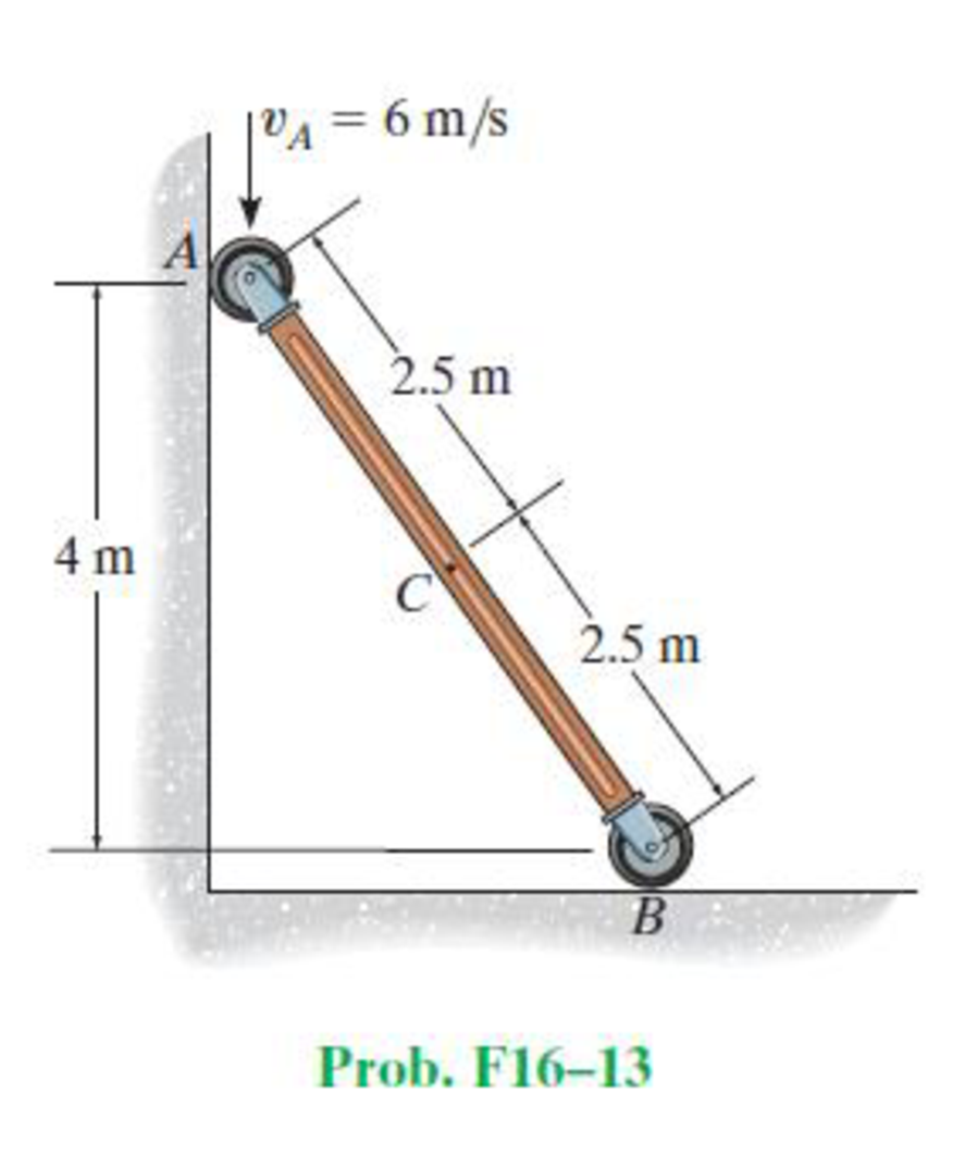
Chapter 16.6, Problem 13FP
Determine the angular velocity of the rod and the velocity of point C at the instant shown.
Expert Solution & Answer

Trending nowThis is a popular solution!

Students have asked these similar questions
Q.2: (15 Marks)
=
1400
For the following system, determine the first natural frequency using Dunkerley's equation,
Given that the disk has moment of inertia J = 2 kg.m², the shaft has G = 20 GPa, p
kg/m³, polar moment of cross-sectional area of the shaft Ip = 8×10⁸ m².
500 mm
220 mm
k=200 N/m
FOF
m=1 kg
14.14
56.56. W
сл
1 Revolute four-bar mechanism, AB=60mm, BC=130mm, CD=140mm, AD=200mm,
CORRECT AND DETAILED HANDWRITTEN SOLUTION WITH FBD ONLY. I WILL UPVOTE THANK YOU. CORRECT ANSWER IS ALREADY PROVIDED.
The roof truss shown carries roof loads, where P = 10 kN. The truss is consisting of circular arcs top andbottom chords with radii R + h and R, respectively.Given: h = 1.2 m, R = 10 m, s = 2 m.Allowable member stresses:Tension = 250 MPaCompression = 180 MPa1. If member KL has square section, determine the minimum dimension (mm).2. If member KL has circular section, determine the minimum diameter (mm).3. If member GH has circular section, determine the minimum diameter (mm).ANSWERS: (1) 31.73 mm; (2) 35.81 mm; (3) 18.49 mm
Chapter 16 Solutions
Engineering Mechanics: Dynamics (14th Edition)
Ch. 16.3 - Determine its constant angular acceleration and...Ch. 16.3 - Determine the angular acceleration when it has...Ch. 16.3 - Determine the time it takes to achieve an angular...Ch. 16.3 - If the angular displacement of the wheel is =...Ch. 16.3 - Determine the magnitude of the velocity and...Ch. 16.3 - Determine the velocity of the cylinder and the...Ch. 16.3 - Determine the magnitudes of the velocity and...Ch. 16.3 - If the disk is originally rotating at 0 = 12...Ch. 16.3 - It it is subjected to a constant angular...Ch. 16.3 - If it is subjected to a constant angular...
Ch. 16.3 - Determine the number of revolutions, the angular...Ch. 16.3 - Determine the number of revolutions it must...Ch. 16.3 - Also, find the number of revolutions of gear D to...Ch. 16.3 - Gears A, B, C, and D have radii of 15 mm, 50 mm,...Ch. 16.3 - Determine the magnitude of acceleration of point B...Ch. 16.3 - pulley A is given a constant angular acceleration...Ch. 16.3 - Starting from rest, determine the angular...Ch. 16.3 - If the engine turns pulley A at A = (20t + 40)...Ch. 16.3 - If the engine turns pulley A at A = 60 rad/s,...Ch. 16.3 - Determine the angular velocity of the disk and its...Ch. 16.3 - Determine the magnitudes of the normal and...Ch. 16.3 - Determine the magnitudes of the normal and...Ch. 16.3 - If this gear is initially turning at A = 15 rad/s,...Ch. 16.3 - If this gear is initially turning at A = 15 rad/s,...Ch. 16.3 - Determine the brushs angular velocity when t = 4...Ch. 16.3 - If this gear is initially turning at (A)0 = 20...Ch. 16.3 - Determine the magnitudes of the velocity and the n...Ch. 16.3 - If the motor turns gear A with an angular...Ch. 16.3 - If the motor turns gear A with an angular...Ch. 16.3 - and the meshed pinion gear B on the propeller...Ch. 16.3 - determine the magnitude of the velocity and...Ch. 16.3 - If the gears A and have the dimensions shown,...Ch. 16.3 - and the meshed pinion gear B on the propeller...Ch. 16.3 - and the meshed pinion gear B on the propeller...Ch. 16.3 - If the canisters are centered 200 mm apart on the...Ch. 16.3 - Determine the largest angular velocity of gear B...Ch. 16.3 - The shaft of the motor M turns with an angular...Ch. 16.3 - If A has a constant angular acceleration of A = 30...Ch. 16.3 - If the angular displacement of A it A = (5t3 +...Ch. 16.3 - This gear is connected to gear B, which is fixed...Ch. 16.3 - Express the result in Cartesian vector form.Ch. 16.3 - Determine the velocity and acceleration of point D...Ch. 16.3 - At the instant shown it is rotating about the y...Ch. 16.3 - Determine the magnitudes of the velocity and...Ch. 16.4 - Determine the angular velocity and angular...Ch. 16.4 - Determine the angular acceleration and angular...Ch. 16.4 - Determine the angular acceleration and angular...Ch. 16.4 - Determine the angular velocity and angular...Ch. 16.4 - Determine the angular velocity of the connecting...Ch. 16.4 - The cam rotates with a constant counterclockwise...Ch. 16.4 - The pin connection at O does not cause an...Ch. 16.4 - Determine the velocity of the follower rod AB as...Ch. 16.4 - The pin connection at O does not cause an...Ch. 16.4 - Determine the velocity and acceleration of the peg...Ch. 16.4 - Determine the velocity and acceleration of block...Ch. 16.4 - Determine the angular velocity and angular...Ch. 16.4 - If the slotted arm is causing A to move downward...Ch. 16.4 - If the wedge moves to the left with a constant...Ch. 16.4 - If the rollers do not slip, determine their...Ch. 16.4 - If no slipping occurs between the disk D and the...Ch. 16.4 - Determine the velocity and acceleration of...Ch. 16.5 - If roller A moves to the right with a constant...Ch. 16.5 - Determine the magnitude of the velocity of point B...Ch. 16.5 - The cable wraps around the inner core, and the...Ch. 16.5 - If crank OA rotates with an angular velocity of =...Ch. 16.5 - If rod AB slides along the horizontal slot with a...Ch. 16.5 - Determine the velocity of the peg at B at this...Ch. 16.5 - Determine the velocity of point B at this instant.Ch. 16.5 - If the block at C is moving downward at 4 ft/s,...Ch. 16.5 - Determine the velocity of block C and the angular...Ch. 16.5 - Determine the angular velocities of links A B and...Ch. 16.5 - Also, sketch the position of link BC when = 55,...Ch. 16.5 - Link BC rotates clockwise with an angular velocity...Ch. 16.5 - If the angular velocity of link AB is AB = 3...Ch. 16.5 - Determine the velocity of the gear rack C.Ch. 16.5 - If B is moving to the right at 8 ft/s and C is...Ch. 16.5 - Determine the angular velocity of the gear and the...Ch. 16.5 - Determine the velocity of point A on the rim of...Ch. 16.5 - Link CB is horizontal at this instant.Ch. 16.5 - Determine the velocity of the slider C at the...Ch. 16.5 - Determine the velocity of block C and the angular...Ch. 16.5 - If AB has an angular velocity AB = 8 rad/s,...Ch. 16.5 - If the slider block A is moving downward at vA = 4...Ch. 16.5 - If the slider block A is moving downward at A = 4...Ch. 16.5 - This gear has an inner hub C which is fixed to B...Ch. 16.5 - If link AB is rotating at AB =3 rad/s, determine...Ch. 16.5 - If link CD is rotating at CD = 5 rad/s, determine...Ch. 16.5 - By locking or releasing certain gears, it has the...Ch. 16.5 - If the ring gear A rotates clockwise with an...Ch. 16.5 - It consists of a driving piston A, three links,...Ch. 16.5 - Because of the rotational motion of lint AB and...Ch. 16.6 - Establish the location of the instantaneous center...Ch. 16.6 - Determine the angular velocity of the rod and the...Ch. 16.6 - Determine the angular velocity of link BC and...Ch. 16.6 - The gear rack B is fixed.Ch. 16.6 - If cable AB is unwound with a speed of 3 m/s, and...Ch. 16.6 - Determine the angular velocity of link BC and the...Ch. 16.6 - Determine the angular velocity of links BC and CD...Ch. 16.6 - Assume the geometry is known.Ch. 16.6 - Determine the angular velocity of link AB at the...Ch. 16.6 - Determine the angular velocity of the link CB at...Ch. 16.6 - Determine the velocities of the cylinders center C...Ch. 16.6 - Determine the velocities of points A and B on the...Ch. 16.6 - Determine the velocities of points A and B.Ch. 16.6 - If rod CD is rotating with an angular velocity CD...Ch. 16.6 - If bar AB has an angular velocity AB = 6 rad/s,...Ch. 16.6 - Under these conditions, what is the speed at A if...Ch. 16.6 - Due to slipping, points A and B on the rim of the...Ch. 16.6 - Determine the velocities of the center point C and...Ch. 16.6 - Determine the velocity of point D and the angular...Ch. 16.6 - Determine the velocity of point P, and the angular...Ch. 16.6 - If connected bar CD is rotating with an angular...Ch. 16.6 - Determine the speeds of points A, B, and C caused...Ch. 16.6 - Determine the velocity of the gear rack C.Ch. 16.6 - If the hub gear H and ring gear R have angular...Ch. 16.6 - What is the angular velocity of the spur gear?Ch. 16.6 - Determine the angular velocity of rod CD at the...Ch. 16.6 - If bar CD is rotating with an angular velocity of...Ch. 16.6 - If the link rotates about the fixed point B at 4...Ch. 16.7 - if the sun gear D is rotating clockwise at D = 5...Ch. 16.7 - The angular velocity is given.Ch. 16.7 - Determine the angular acceleration of the rod and...Ch. 16.7 - Determine the acceleration of point A.Ch. 16.7 - At the instant shown, the center O of the gear...Ch. 16.7 - Determine the angular acceleration of the gear at...Ch. 16.7 - Determine the angular acceleration of link BC at...Ch. 16.7 - Determine the angular acceleration of link BC and...Ch. 16.7 - Determine the velocity sod acceleration of the...Ch. 16.7 - Determine the acceleration of the top of the...Ch. 16.7 - Determine the acceleration of the bottom A of the...Ch. 16.7 - Determine the velocity and acceleration of the...Ch. 16.7 - Determine the velocity and acceleration of the...Ch. 16.7 - At the instant shown, point A has the motion...Ch. 16.7 - Determine the angular velocity and angular...Ch. 16.7 - Determine the angular velocity and angular...Ch. 16.7 - Determine the angular acceleration of link AB and...Ch. 16.7 - Determine the angular acceleration of link CD if...Ch. 16.7 - Determine the velocity and acceleration of point A...Ch. 16.7 - Determine the velocity and acceleration of point B...Ch. 16.7 - If it is pulled with a constant velocity v,...Ch. 16.7 - If it does not slip at A, determine the...Ch. 16.7 - If it does not slip at A, determine the...Ch. 16.7 - As cord CF unwinds from the inner rim of the...Ch. 16.7 - Determine the velocity and acceleration of point B...Ch. 16.7 - Determine the angular velocity and angular...Ch. 16.7 - If link DE has the angular motion shown, determine...Ch. 16.7 - If member AB has the angular motion shown,...Ch. 16.7 - If member AB has the angular motion shown,...Ch. 16.7 - Determine the acceleration of points A and B on...Ch. 16.7 - At a given instant, A has a velocity of vA = 4...Ch. 16.7 - Determine the angular acceleration of rod AB at...Ch. 16.8 - Determine the acceleration of A at the instant...Ch. 16.8 - If at the same instant the disk has the angular...Ch. 16.8 - At the same instant, the boom is extending with a...Ch. 16.8 - Prob. 131PCh. 16.8 - Prob. 132PCh. 16.8 - Determine the velocity and acceleration of a water...Ch. 16.8 - At the instant shown, the cord is pulled down...Ch. 16.8 - Prob. 135PCh. 16.8 - Determine the velocity and acceleration of point C...Ch. 16.8 - Prob. 137PCh. 16.8 - Determine the magnitudes of the velocity and...Ch. 16.8 - If link AD is rotating at a constant rate of AD =...Ch. 16.8 - Determine the angular velocity and angular...Ch. 16.8 - If rod AB has an angular velocity of 2 rad/s and...Ch. 16.8 - Prob. 142PCh. 16.8 - If the gears center O moves with the velocity and...Ch. 16.8 - Prob. 144PCh. 16.8 - Prob. 145PCh. 16.8 - Also at this instant the car mounted at the end of...Ch. 16.8 - If the slider block C is fixed to the disk that...Ch. 16.8 - Determine the velocity and acceleration of car A...Ch. 16.8 - Determine the velocity and acceleration of car B...Ch. 16.8 - Link AB has a pin at B which is confined to move...Ch. 16.8 - Prob. 151PCh. 16.8 - The star wheel A makes one sixth of a revolution...Ch. 16.8 - If the tires do not slip on the pavement,...Ch. 16.8 - Determine the velocity and deceleration of the...Ch. 16.8 - Determine the speed of block B when it has risen s...Ch. 16.8 - At the instant shown, it has an acceleration of...Ch. 16.8 - If bar AB has an angular velocity AB = 6 rad/s,...Ch. 16.8 - If the cable does not slip on the pulley's...Ch. 16.8 - Determine the acceleration of the pin at C and the...Ch. 16.8 - If it does not slip at A, determine the...Ch. 16.8 - Determine the velocity and acceleration of the...
Knowledge Booster


Learn more about
Need a deep-dive on the concept behind this application? Look no further. Learn more about this topic, mechanical-engineering and related others by exploring similar questions and additional content below.Similar questions
- CORRECT AND DETAILED HANDWRITTEN SOLUTION WITH FBD ONLY. I WILL UPVOTE THANK YOU. CORRECT ANSWER IS ALREADY PROVIDED. The cantilevered spandrel beam shown whose depth tapers from d1 to d2, has a constant width of 120mm. It carries a triangularly distributed end reaction.Given: d1 = 600 mm, d2 = 120 mm, L = 1 m, w = 100 kN/m1. Calculate the maximum flexural stress at the support, in kN-m.2. Determine the distance (m), from the free end, of the section with maximum flexural stress.3. Determine the maximum flexural stress in the beam, in MPa.ANSWERS: (1) 4.630 MPa; (2) 905.8688 m; (3) 4.65 MPaarrow_forwardCORRECT AND DETAILED HANDWRITTEN SOLUTION WITH FBD ONLY. I WILL UPVOTE THANK YOU. CORRECT ANSWER IS ALREADY PROVIDED. A concrete wall retains water as shown. Assume that the wall is fixed at the base. Given: H = 3 m, t = 0.5m, Concrete unit weight = 23 kN/m3Unit weight of water = 9.81 kN/m3(Hint: The pressure of water is linearly increasing from the surface to the bottom with intensity 9.81d.)1. Find the maximum compressive stress (MPa) at the base of the wall if the water reaches the top.2. If the maximum compressive stress at the base of the wall is not to exceed 0.40 MPa, what is the maximum allowable depth(m) of the water?3. If the tensile stress at the base is zero, what is the maximum allowable depth (m) of the water?ANSWERS: (1) 1.13 MPa, (2) 2.0 m, (3) 1.20 marrow_forwardCORRECT AND DETAILED HANDWRITTEN SOLUTION WITH FBD ONLY. I WILL UPVOTE THANK YOU. CORRECT ANSWER IS ALREADY PROVIDED. A short plate is attached to the center of the shaft as shown. The bottom of the shaft is fixed to the ground.Given: a = 75 mm, h = 125 mm, D = 38 mmP1 = 24 kN, P2 = 28 kN1. Calculate the maximum torsional stress in the shaft, in MPa.2. Calculate the maximum flexural stress in the shaft, in MPa.3. Calculate the maximum horizontal shear stress in the shaft, in MPa.ANSWERS: (1) 167.07 MPa; (2) 679.77 MPa; (3) 28.22 MPaarrow_forward
- A counter flow double pipe heat exchanger is being used to cool hot oil from 320°F to 285°F using cold water. The water, which flows through the inner tube, enters the heat exchanger at 70°F and leaves at 175°F. The inner tube is ¾-std type L copper. The overall heat transfer coefficient based on the outside diameter of the inner tube is 140 Btu/hr-ft2-°F. Design conditions call for a total heat transfer duty (heat transfer rate between the two fluids) of 20,000 Btu/hr. Determine the required length of this heat exchanger (ft).arrow_forward! Required information A one-shell-pass and eight-tube-passes heat exchanger is used to heat glycerin (cp=0.60 Btu/lbm.°F) from 80°F to 140°F by hot water (Cp = 1.0 Btu/lbm-°F) that enters the thin-walled 0.5-in-diameter tubes at 175°F and leaves at 120°F. The total length of the tubes in the heat exchanger is 400 ft. The convection heat transfer coefficient is 4 Btu/h-ft²°F on the glycerin (shell) side and 70 Btu/h-ft²°F on the water (tube) side. NOTE: This is a multi-part question. Once an answer is submitted, you will be unable to return to this part. Determine the rate of heat transfer in the heat exchanger before any fouling occurs. Correction factor F 1.0 10 0.9 0.8 R=4.0 3.0 2.0.15 1.0 0.8.0.6 0.4 0.2 0.7 0.6 R= T1-T2 12-11 0.5 12-11 0 0.1 0.2 0.3 0.4 0.5 0.6 0.7 0.8 0.9 1.0 (a) One-shell pass and 2, 4, 6, etc. (any multiple of 2), tube passes P= T₁-11 The rate of heat transfer in the heat exchanger is Btu/h.arrow_forward! Required information Air at 25°C (cp=1006 J/kg.K) is to be heated to 58°C by hot oil at 80°C (cp = 2150 J/kg.K) in a cross-flow heat exchanger with air mixed and oil unmixed. The product of heat transfer surface area and the overall heat transfer coefficient is 750 W/K and the mass flow rate of air is twice that of oil. NOTE: This is a multi-part question. Once an answer is submitted, you will be unable to return to this part. Air Oil 80°C Determine the effectiveness of the heat exchanger.arrow_forward
- In an industrial facility, a counter-flow double-pipe heat exchanger uses superheated steam at a temperature of 155°C to heat feed water at 30°C. The superheated steam experiences a temperature drop of 70°C as it exits the heat exchanger. The water to be heated flows through the heat exchanger tube of negligible thickness at a constant rate of 3.47 kg/s. The convective heat transfer coefficient on the superheated steam and water side is 850 W/m²K and 1250 W/m²K, respectively. To account for the fouling due to chemical impurities that might be present in the feed water, assume a fouling factor of 0.00015 m²-K/W for the water side. The specific heat of water is determined at an average temperature of (30 +70)°C/2 = 50°C and is taken to be J/kg.K. Cp= 4181 Water Steam What would be the required heat exchanger area in case of parallel-flow arrangement? The required heat exchanger area in case of parallel-flow arrangement is 1m².arrow_forwardA single-pass crossflow heat exchanger is used to cool jacket water (cp = 1.0 Btu/lbm.°F) of a diesel engine from 190°F to 140°F, using air (Cp = 0.245 Btu/lbm.°F) at inlet temperature of 90°F. Both air flow and water flow are unmixed. If the water and air mass flow rates are 85500 lbm/h and 400,000 lbm/h, respectively, determine the log mean temperature difference for this heat exchanger. Assume the correction factor F to be 0.92. Air flow (unmixed) Water flow (unmixed) The log mean temperature difference of the heat exchanger is °F.arrow_forwardusing the theorem of three moments, find all the reactions and supports, I need concise calculations only. the answers are at the bottom, I need concise steps and minimal explanationsarrow_forward
- In an industrial facility, a counter-flow double-pipe heat exchanger uses superheated steam at a temperature of 155°C to heat feed water at 30°C. The superheated steam experiences a temperature drop of 70°C as it exits the heat exchanger. The water to be heated flows through the heat exchanger tube of negligible thickness at a constant rate of 3.47 kg/s. The convective heat transfer coefficient on the superheated steam and water side is 850 W/m²K and 1250 W/m²K, respectively. To account for the fouling due to chemical impurities that might be present in the feed water, assume a fouling factor of 0.00015 m² K/W for the water side. The specific heat of water is determined at an average temperature of (30+70)°C/2 = 50°C and is taken to be Cp J/kg-K. Water Steam Determine the heat exchanger area required to maintain the exit temperature of the water to a minimum of 70°C. The heat exchanger area required isarrow_forwardStress, ksi 160 72 150- 140 80 70 ༄ ྃ ༈ ཎྜ རྦ ༅ ཎྜ ྣཧྨ ➢ 130 120 110 100 90 2.0 2.8 3.6 4.4 5 Wire diameter, mm 6.0 6.8 2 7.6 8.4 Compression and extension springs. ASTM A227 Class II Light service Average service 0.020 0.060 0.100 0.140 0.180 0.220 0.260 0.300 0.340 0.380 0.420 0.460 0.500 Wire diameter, in Torsional stress due to initial tension, ksi 10 ४ 20 Preferred range 100 Stress, MPa 9.2 10.0 10.8 11.6 12.4 1100 1035 965 895 825 760 Severe service 690 620 550 50 150 3456789 10 11 12 13 14 15 16 Spring index, C = DJD FIGURE 18-21 Recommended torsional shear stress in an extension spring due to initial tension (Data from Associated Spring, Barnes Group, Inc.) 50 200 485 Stress, MPaarrow_forwardBolted Joint Design Bolted Frames Total Force due to door weight: P = 240 lb Number of Bolts: N = Distance to Bolt C/L: a = 4 N/A Bolt Material - Allowable shear stress of bolt material: T₂ = x Distance from Bolt centroid to bolt: x = y Distance from Bolt centroid to bolt: y = Degrees per Radian- Results y-Load on each bolt: F, = Moment resisted by bolt pattern: M = Radial distance from Bolt centroid to bolt: r = Sum squares of all radial distances: Σr² Force on each bolt to resist moment: F, - Angle for force composition: e= X-Force on each bolt to resist moment: F- y-Force on each bolt to resist moment: Fly Total y-Force on each bolt: Fy = Resultant force on bolt 1: R₁ = Required shear stress area for a bolt: A₂ = ASTM Grade A307 Steel 10,000 0 psi from Table 20-1 3.0 57.296 in degrees lb per bolt lb-in Formula FS-P/N M-Px XB r = (x² + y²)0.5 in² Σ 4r² Mr F₁ = Στ lb degrees lb lb lb Minimum Bolt Diameter: Din = Rounded up Bolt Diameter: D = 55 P. 1.5 in 2 in (3x) 1 in This bracket…arrow_forward
arrow_back_ios
SEE MORE QUESTIONS
arrow_forward_ios
Recommended textbooks for you
 Elements Of ElectromagneticsMechanical EngineeringISBN:9780190698614Author:Sadiku, Matthew N. O.Publisher:Oxford University Press
 Mechanics of Materials (10th Edition)Mechanical EngineeringISBN:9780134319650Author:Russell C. HibbelerPublisher:PEARSON
 Thermodynamics: An Engineering ApproachMechanical EngineeringISBN:9781259822674Author:Yunus A. Cengel Dr., Michael A. BolesPublisher:McGraw-Hill Education
 Control Systems EngineeringMechanical EngineeringISBN:9781118170519Author:Norman S. NisePublisher:WILEY
 Mechanics of Materials (MindTap Course List)Mechanical EngineeringISBN:9781337093347Author:Barry J. Goodno, James M. GerePublisher:Cengage Learning
 Engineering Mechanics: StaticsMechanical EngineeringISBN:9781118807330Author:James L. Meriam, L. G. Kraige, J. N. BoltonPublisher:WILEY
Elements Of Electromagnetics
Mechanical Engineering
ISBN:9780190698614
Author:Sadiku, Matthew N. O.
Publisher:Oxford University Press
Mechanics of Materials (10th Edition)
Mechanical Engineering
ISBN:9780134319650
Author:Russell C. Hibbeler
Publisher:PEARSON
Thermodynamics: An Engineering Approach
Mechanical Engineering
ISBN:9781259822674
Author:Yunus A. Cengel Dr., Michael A. Boles
Publisher:McGraw-Hill Education
Control Systems Engineering
Mechanical Engineering
ISBN:9781118170519
Author:Norman S. Nise
Publisher:WILEY
Mechanics of Materials (MindTap Course List)
Mechanical Engineering
ISBN:9781337093347
Author:Barry J. Goodno, James M. Gere
Publisher:Cengage Learning
Engineering Mechanics: Statics
Mechanical Engineering
ISBN:9781118807330
Author:James L. Meriam, L. G. Kraige, J. N. Bolton
Publisher:WILEY
Dynamics - Lesson 1: Introduction and Constant Acceleration Equations; Author: Jeff Hanson;https://www.youtube.com/watch?v=7aMiZ3b0Ieg;License: Standard YouTube License, CC-BY