Engineering Mechanics: Dynamics (14th Edition)
14th Edition
ISBN: 9780133915389
Author: Russell C. Hibbeler
Publisher: PEARSON
expand_more
expand_more
format_list_bulleted
Concept explainers
Videos
Textbook Question
Chapter 16.5, Problem 12FP
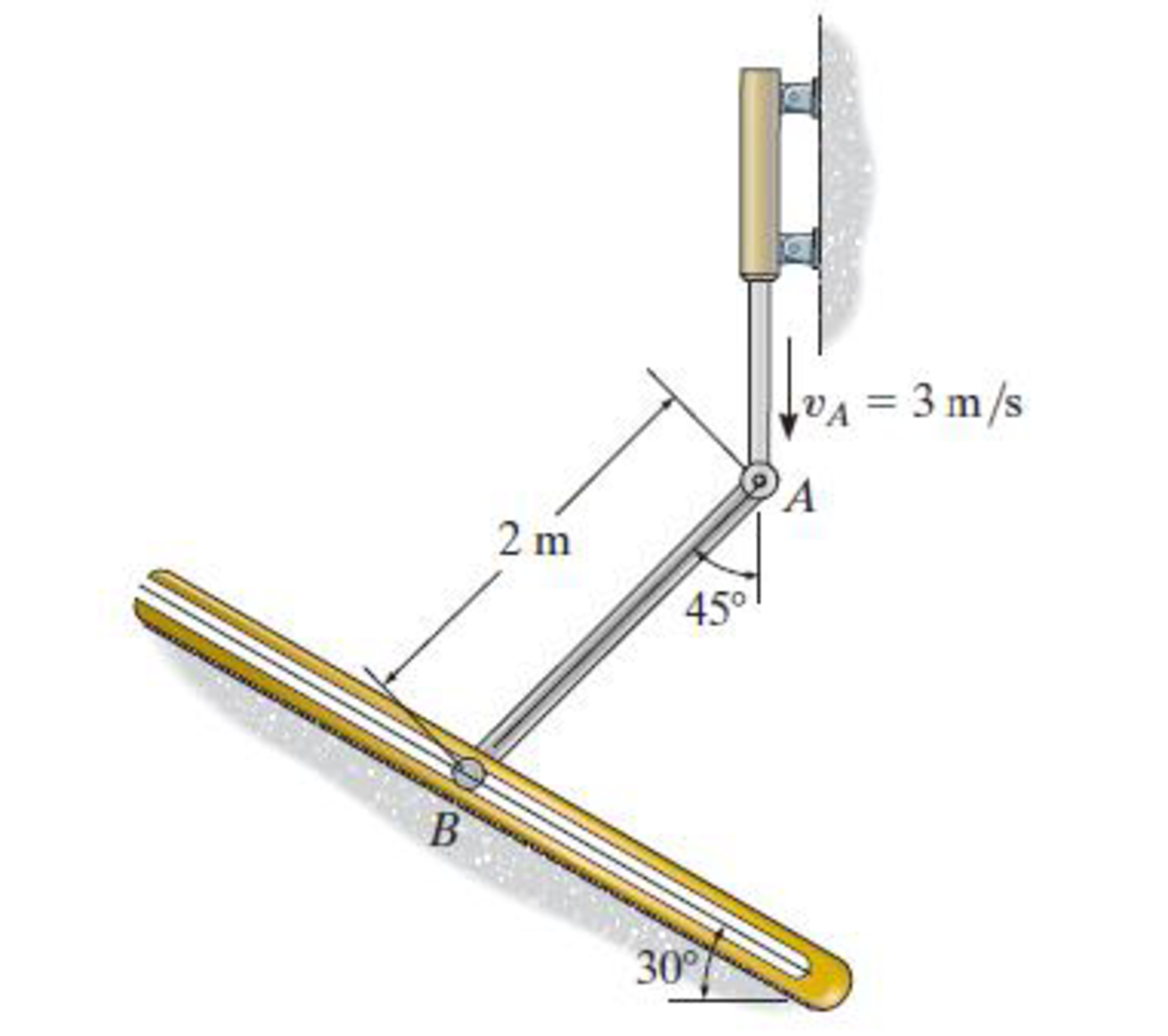
Determine the velocity of the peg at B at this instant. The peg is constrained to move along the slot.
Expert Solution & Answer
Want to see the full answer?
Check out a sample textbook solution
Students have asked these similar questions
mylabmastering.pearson.com
Chapter 12 - Lecture Notes.pptx: (MAE 272-01) (SP25) DY...
P Pearson MyLab and Mastering
Scores
K
mylabmastering.pearson.com
Chapter 12 - Lecture Notes.pptx: (MAE 272-01) (SP25) DY...
P Pearson MyLab and Mastering
Mastering Engineering
Back to my courses
Course Home
Scores
Course Home
K
mylabmastering.pearson.com
Chapter 12 - Lecture Notes.pptx: (MAE 272-01) (SP25) DY...
P Pearson MyLab and Mastering
Mastering Engineering
Back to my courses
Course Home
Scores
Course Home
Chapter 16 Solutions
Engineering Mechanics: Dynamics (14th Edition)
Ch. 16.3 - Determine its constant angular acceleration and...Ch. 16.3 - Determine the angular acceleration when it has...Ch. 16.3 - Determine the time it takes to achieve an angular...Ch. 16.3 - If the angular displacement of the wheel is =...Ch. 16.3 - Determine the magnitude of the velocity and...Ch. 16.3 - Determine the velocity of the cylinder and the...Ch. 16.3 - Determine the magnitudes of the velocity and...Ch. 16.3 - If the disk is originally rotating at 0 = 12...Ch. 16.3 - It it is subjected to a constant angular...Ch. 16.3 - If it is subjected to a constant angular...
Ch. 16.3 - Determine the number of revolutions, the angular...Ch. 16.3 - Determine the number of revolutions it must...Ch. 16.3 - Also, find the number of revolutions of gear D to...Ch. 16.3 - Gears A, B, C, and D have radii of 15 mm, 50 mm,...Ch. 16.3 - Determine the magnitude of acceleration of point B...Ch. 16.3 - pulley A is given a constant angular acceleration...Ch. 16.3 - Starting from rest, determine the angular...Ch. 16.3 - If the engine turns pulley A at A = (20t + 40)...Ch. 16.3 - If the engine turns pulley A at A = 60 rad/s,...Ch. 16.3 - Determine the angular velocity of the disk and its...Ch. 16.3 - Determine the magnitudes of the normal and...Ch. 16.3 - Determine the magnitudes of the normal and...Ch. 16.3 - If this gear is initially turning at A = 15 rad/s,...Ch. 16.3 - If this gear is initially turning at A = 15 rad/s,...Ch. 16.3 - Determine the brushs angular velocity when t = 4...Ch. 16.3 - If this gear is initially turning at (A)0 = 20...Ch. 16.3 - Determine the magnitudes of the velocity and the n...Ch. 16.3 - If the motor turns gear A with an angular...Ch. 16.3 - If the motor turns gear A with an angular...Ch. 16.3 - and the meshed pinion gear B on the propeller...Ch. 16.3 - determine the magnitude of the velocity and...Ch. 16.3 - If the gears A and have the dimensions shown,...Ch. 16.3 - and the meshed pinion gear B on the propeller...Ch. 16.3 - and the meshed pinion gear B on the propeller...Ch. 16.3 - If the canisters are centered 200 mm apart on the...Ch. 16.3 - Determine the largest angular velocity of gear B...Ch. 16.3 - The shaft of the motor M turns with an angular...Ch. 16.3 - If A has a constant angular acceleration of A = 30...Ch. 16.3 - If the angular displacement of A it A = (5t3 +...Ch. 16.3 - This gear is connected to gear B, which is fixed...Ch. 16.3 - Express the result in Cartesian vector form.Ch. 16.3 - Determine the velocity and acceleration of point D...Ch. 16.3 - At the instant shown it is rotating about the y...Ch. 16.3 - Determine the magnitudes of the velocity and...Ch. 16.4 - Determine the angular velocity and angular...Ch. 16.4 - Determine the angular acceleration and angular...Ch. 16.4 - Determine the angular acceleration and angular...Ch. 16.4 - Determine the angular velocity and angular...Ch. 16.4 - Determine the angular velocity of the connecting...Ch. 16.4 - The cam rotates with a constant counterclockwise...Ch. 16.4 - The pin connection at O does not cause an...Ch. 16.4 - Determine the velocity of the follower rod AB as...Ch. 16.4 - The pin connection at O does not cause an...Ch. 16.4 - Determine the velocity and acceleration of the peg...Ch. 16.4 - Determine the velocity and acceleration of block...Ch. 16.4 - Determine the angular velocity and angular...Ch. 16.4 - If the slotted arm is causing A to move downward...Ch. 16.4 - If the wedge moves to the left with a constant...Ch. 16.4 - If the rollers do not slip, determine their...Ch. 16.4 - If no slipping occurs between the disk D and the...Ch. 16.4 - Determine the velocity and acceleration of...Ch. 16.5 - If roller A moves to the right with a constant...Ch. 16.5 - Determine the magnitude of the velocity of point B...Ch. 16.5 - The cable wraps around the inner core, and the...Ch. 16.5 - If crank OA rotates with an angular velocity of =...Ch. 16.5 - If rod AB slides along the horizontal slot with a...Ch. 16.5 - Determine the velocity of the peg at B at this...Ch. 16.5 - Determine the velocity of point B at this instant.Ch. 16.5 - If the block at C is moving downward at 4 ft/s,...Ch. 16.5 - Determine the velocity of block C and the angular...Ch. 16.5 - Determine the angular velocities of links A B and...Ch. 16.5 - Also, sketch the position of link BC when = 55,...Ch. 16.5 - Link BC rotates clockwise with an angular velocity...Ch. 16.5 - If the angular velocity of link AB is AB = 3...Ch. 16.5 - Determine the velocity of the gear rack C.Ch. 16.5 - If B is moving to the right at 8 ft/s and C is...Ch. 16.5 - Determine the angular velocity of the gear and the...Ch. 16.5 - Determine the velocity of point A on the rim of...Ch. 16.5 - Link CB is horizontal at this instant.Ch. 16.5 - Determine the velocity of the slider C at the...Ch. 16.5 - Determine the velocity of block C and the angular...Ch. 16.5 - If AB has an angular velocity AB = 8 rad/s,...Ch. 16.5 - If the slider block A is moving downward at vA = 4...Ch. 16.5 - If the slider block A is moving downward at A = 4...Ch. 16.5 - This gear has an inner hub C which is fixed to B...Ch. 16.5 - If link AB is rotating at AB =3 rad/s, determine...Ch. 16.5 - If link CD is rotating at CD = 5 rad/s, determine...Ch. 16.5 - By locking or releasing certain gears, it has the...Ch. 16.5 - If the ring gear A rotates clockwise with an...Ch. 16.5 - It consists of a driving piston A, three links,...Ch. 16.5 - Because of the rotational motion of lint AB and...Ch. 16.6 - Establish the location of the instantaneous center...Ch. 16.6 - Determine the angular velocity of the rod and the...Ch. 16.6 - Determine the angular velocity of link BC and...Ch. 16.6 - The gear rack B is fixed.Ch. 16.6 - If cable AB is unwound with a speed of 3 m/s, and...Ch. 16.6 - Determine the angular velocity of link BC and the...Ch. 16.6 - Determine the angular velocity of links BC and CD...Ch. 16.6 - Assume the geometry is known.Ch. 16.6 - Determine the angular velocity of link AB at the...Ch. 16.6 - Determine the angular velocity of the link CB at...Ch. 16.6 - Determine the velocities of the cylinders center C...Ch. 16.6 - Determine the velocities of points A and B on the...Ch. 16.6 - Determine the velocities of points A and B.Ch. 16.6 - If rod CD is rotating with an angular velocity CD...Ch. 16.6 - If bar AB has an angular velocity AB = 6 rad/s,...Ch. 16.6 - Under these conditions, what is the speed at A if...Ch. 16.6 - Due to slipping, points A and B on the rim of the...Ch. 16.6 - Determine the velocities of the center point C and...Ch. 16.6 - Determine the velocity of point D and the angular...Ch. 16.6 - Determine the velocity of point P, and the angular...Ch. 16.6 - If connected bar CD is rotating with an angular...Ch. 16.6 - Determine the speeds of points A, B, and C caused...Ch. 16.6 - Determine the velocity of the gear rack C.Ch. 16.6 - If the hub gear H and ring gear R have angular...Ch. 16.6 - What is the angular velocity of the spur gear?Ch. 16.6 - Determine the angular velocity of rod CD at the...Ch. 16.6 - If bar CD is rotating with an angular velocity of...Ch. 16.6 - If the link rotates about the fixed point B at 4...Ch. 16.7 - if the sun gear D is rotating clockwise at D = 5...Ch. 16.7 - The angular velocity is given.Ch. 16.7 - Determine the angular acceleration of the rod and...Ch. 16.7 - Determine the acceleration of point A.Ch. 16.7 - At the instant shown, the center O of the gear...Ch. 16.7 - Determine the angular acceleration of the gear at...Ch. 16.7 - Determine the angular acceleration of link BC at...Ch. 16.7 - Determine the angular acceleration of link BC and...Ch. 16.7 - Determine the velocity sod acceleration of the...Ch. 16.7 - Determine the acceleration of the top of the...Ch. 16.7 - Determine the acceleration of the bottom A of the...Ch. 16.7 - Determine the velocity and acceleration of the...Ch. 16.7 - Determine the velocity and acceleration of the...Ch. 16.7 - At the instant shown, point A has the motion...Ch. 16.7 - Determine the angular velocity and angular...Ch. 16.7 - Determine the angular velocity and angular...Ch. 16.7 - Determine the angular acceleration of link AB and...Ch. 16.7 - Determine the angular acceleration of link CD if...Ch. 16.7 - Determine the velocity and acceleration of point A...Ch. 16.7 - Determine the velocity and acceleration of point B...Ch. 16.7 - If it is pulled with a constant velocity v,...Ch. 16.7 - If it does not slip at A, determine the...Ch. 16.7 - If it does not slip at A, determine the...Ch. 16.7 - As cord CF unwinds from the inner rim of the...Ch. 16.7 - Determine the velocity and acceleration of point B...Ch. 16.7 - Determine the angular velocity and angular...Ch. 16.7 - If link DE has the angular motion shown, determine...Ch. 16.7 - If member AB has the angular motion shown,...Ch. 16.7 - If member AB has the angular motion shown,...Ch. 16.7 - Determine the acceleration of points A and B on...Ch. 16.7 - At a given instant, A has a velocity of vA = 4...Ch. 16.7 - Determine the angular acceleration of rod AB at...Ch. 16.8 - Determine the acceleration of A at the instant...Ch. 16.8 - If at the same instant the disk has the angular...Ch. 16.8 - At the same instant, the boom is extending with a...Ch. 16.8 - Prob. 131PCh. 16.8 - Prob. 132PCh. 16.8 - Determine the velocity and acceleration of a water...Ch. 16.8 - At the instant shown, the cord is pulled down...Ch. 16.8 - Prob. 135PCh. 16.8 - Determine the velocity and acceleration of point C...Ch. 16.8 - Prob. 137PCh. 16.8 - Determine the magnitudes of the velocity and...Ch. 16.8 - If link AD is rotating at a constant rate of AD =...Ch. 16.8 - Determine the angular velocity and angular...Ch. 16.8 - If rod AB has an angular velocity of 2 rad/s and...Ch. 16.8 - Prob. 142PCh. 16.8 - If the gears center O moves with the velocity and...Ch. 16.8 - Prob. 144PCh. 16.8 - Prob. 145PCh. 16.8 - Also at this instant the car mounted at the end of...Ch. 16.8 - If the slider block C is fixed to the disk that...Ch. 16.8 - Determine the velocity and acceleration of car A...Ch. 16.8 - Determine the velocity and acceleration of car B...Ch. 16.8 - Link AB has a pin at B which is confined to move...Ch. 16.8 - Prob. 151PCh. 16.8 - The star wheel A makes one sixth of a revolution...Ch. 16.8 - If the tires do not slip on the pavement,...Ch. 16.8 - Determine the velocity and deceleration of the...Ch. 16.8 - Determine the speed of block B when it has risen s...Ch. 16.8 - At the instant shown, it has an acceleration of...Ch. 16.8 - If bar AB has an angular velocity AB = 6 rad/s,...Ch. 16.8 - If the cable does not slip on the pulley's...Ch. 16.8 - Determine the acceleration of the pin at C and the...Ch. 16.8 - If it does not slip at A, determine the...Ch. 16.8 - Determine the velocity and acceleration of the...
Knowledge Booster


Learn more about
Need a deep-dive on the concept behind this application? Look no further. Learn more about this topic, mechanical-engineering and related others by exploring similar questions and additional content below.Similar questions
- Chapter 12 - Lecture Notes.pptx: (MAE 272-01) (SP25) DY... Scoresarrow_forwardIn a single cylinder, four stroke, single acting gas engine, the cylinder diameter is 180 mm and the stroke is 350 mm . When running at 250 rpm , the mean area of the indicator diagram taken off the engine is 355 mm² , length of diagram 75 mm , scale of the indicator spring 90 kN/m sq per mm , and the number of explosions was counted to be 114 per minute. Calculate the indicated power. so i have already asked this question and got a good answer, however on step 4, i dont understand how they reached 18.43 KW. When i do the math provided, i get the answer 7195.566. Where am i going wrong? thanks StepsTo clarify how we determined the Indicated Power, I'll go over each step in detail. Step 1: Comprehending the Provided Information - Cylinder diameter (in meters) = 180 mm = 0.18 m - Stroke length (in meters) = 350 mm = 0.35 m - Engine speed = 250 rpm -Indicator diagram mean area = 355 mm² The diagram's length is 75 mm; its spring scale is 90 kN/m² per mm, or 90,000 N/m² per mm; and…arrow_forwardIn MATLAB, can you help me simulate an orbit under earth J2 perturbation with the Milankovich orbital elements? Also, can you check to see if they fit the Milankovich constraint equaiton?arrow_forward
- 8. All of the members in the Warren truss of Figure 8 are of length 10 ft. Use the method of sections to determine the forces in the members BD,CD,CE. B A C D E F G 2000 lb 3000 lb 5000 lb Figure 8 Harrow_forwardAn acrobat is walking on a tightrope of length L =20.1 m attached to supports A and B at a distance of 20.0 m apart. The combined weight of the acrobat and his balancing pole is 900 N, and the friction between his shoes and the rope is large enough to prevent him from slipping. Neglecting the weight of the rope and any elastic deformation, determine the deflection (y) and the tension in portion AC and BC of the rope for values of x from 0.5 m to 10 m using 0.5 m increments. 1. Determine the maximum deflection (y) in the rope. 2. Plot tension of AC and BC vs. x (on the same plot with x on the x-axis). Turn in the plot and the table of x, TAC, and TBC (clearly label each). A C 20.0 m Barrow_forward5. A 4000 lb block of concrete is attached by light inextensible cables to the truss in Figure 5. Determine the force in each member. State whether each member is in tension or compression. 3 ΘΑ D E cables all dimensions in feet.arrow_forward
- A block hangs from the end of bar AB that is 5.80 meters long and connected to the wall in the xz plane. The bar is supported at end A by a ball joint such that it carries only a compressive force along its axis. The bar is supported in equilibrium at end B by cables BD and BC that connect to the xz plane at points C and D respectively with coordinates given in the figure. The z components of the moments exerted on the bar by these two cables sum to 0. The tension in cable BD is measured to be 210 Newtons. Input answers of zero as 0.00 to avoid an invalid answer due to significant figures. Determine the equivalent force and couple system acting at A that models only the forces exerted by both cables BD → and BC on the bar at B. Enter your results for Feq and Meg in Cartesian Components. Z D (c, 0, d) C (a, 0, b). X A f m B y cc 040 BY NC SA 2016 Eric Davishahl Values for dimensions on the figure are given in the following table. Note the figure may not be to scale. Variable Value a…arrow_forwardA bent tube is attached to a wall with brackets as shown. A force of F = 785 lb is applied to the end of the tube with direction indicated by the dimensions in the figure. a.) Determine the moment about point D due to the force F Enter your answer in Cartesian components with units of ft- lbs. b.) Determine the moment about a line (i.e. axis) running from D to C due to the force F. Enter your answer in Cartesian components with units of ft-lbs. 2013 Michael Swanbom x BY NC SA g Z h A с FK kaz Values for dimensions on the figure are given in the table below. Note the figure may not be to scale. Be sure to align your cartesian unit vectors with the coordinate axes shown in the figure. Variable Value α 4.84 in b 13.2 in с 12.5 in d 30.8 in h 18.7 in 22.0 in →> a. MD=( i+ k) ft- lb →> b. MDC = î + k) ft- lbarrow_forwardF1 3 4 5 P F2 F2 Ꮎ e b 200 3 4 5 F1 The electric pole is subject to the forces shown. Force F1 245 N and force F2 = 310 N with an angle 0 = 20.2°. Determine the moment about point P of all forces. Take counterclockwise moments to be positive. = Values for dimensions on the figure are given in the following table. Note the figure may not be to scale. Variable Value a 2.50 m b 11.3 m с 13.0 m The moment about point P is m. N- If the moment about point P sums up to be zero. Determine the distance c while all other values remained the same. m.arrow_forward
- F y b C 10 Z Determine the moment about O due to the force F shown, the magnitude of the force F = 76.0 lbs. Note: Pay attention to the axis. Values for dimensions on the figure are given in the following table. Note the figure may not be to scale. Variable Value a 1.90 ft b 2.80 ft с 2.60 ft d 2.30 ft Mo = lb + k) ft-arrow_forwardThe shelf bracket is subjected to the force F = 372 Newtons at an angle = 21.4°. Compute the moment (in N-m) that this force exerts about each of the two attachment points (screw locations in the figure). Take counterclockwise moments to be positive. a duk F -0 2013 cc Michael Swanbom BY NC O SA Values for dimensions on the figure are given in the following table. Note the figure may not be to scale. Variable Value a 43.0 cm b 32.3 cm с 2.58 cm The moment about the upper attachment point is N-m. The moment about the lower attachment point is N-m.arrow_forwardA man skis down a slope. His initial elevation was 150 m and his velocity at the bottom of the slope is 17 m/s. What percentage of his initial potential energy was consumed due to friction and air resistance? Use the accounting equation in your calculations.arrow_forward
arrow_back_ios
SEE MORE QUESTIONS
arrow_forward_ios
Recommended textbooks for you
 Elements Of ElectromagneticsMechanical EngineeringISBN:9780190698614Author:Sadiku, Matthew N. O.Publisher:Oxford University Press
 Mechanics of Materials (10th Edition)Mechanical EngineeringISBN:9780134319650Author:Russell C. HibbelerPublisher:PEARSON
 Thermodynamics: An Engineering ApproachMechanical EngineeringISBN:9781259822674Author:Yunus A. Cengel Dr., Michael A. BolesPublisher:McGraw-Hill Education
 Control Systems EngineeringMechanical EngineeringISBN:9781118170519Author:Norman S. NisePublisher:WILEY
 Mechanics of Materials (MindTap Course List)Mechanical EngineeringISBN:9781337093347Author:Barry J. Goodno, James M. GerePublisher:Cengage Learning
 Engineering Mechanics: StaticsMechanical EngineeringISBN:9781118807330Author:James L. Meriam, L. G. Kraige, J. N. BoltonPublisher:WILEY
Elements Of Electromagnetics
Mechanical Engineering
ISBN:9780190698614
Author:Sadiku, Matthew N. O.
Publisher:Oxford University Press
Mechanics of Materials (10th Edition)
Mechanical Engineering
ISBN:9780134319650
Author:Russell C. Hibbeler
Publisher:PEARSON
Thermodynamics: An Engineering Approach
Mechanical Engineering
ISBN:9781259822674
Author:Yunus A. Cengel Dr., Michael A. Boles
Publisher:McGraw-Hill Education
Control Systems Engineering
Mechanical Engineering
ISBN:9781118170519
Author:Norman S. Nise
Publisher:WILEY
Mechanics of Materials (MindTap Course List)
Mechanical Engineering
ISBN:9781337093347
Author:Barry J. Goodno, James M. Gere
Publisher:Cengage Learning
Engineering Mechanics: Statics
Mechanical Engineering
ISBN:9781118807330
Author:James L. Meriam, L. G. Kraige, J. N. Bolton
Publisher:WILEY
Dynamics - Lesson 1: Introduction and Constant Acceleration Equations; Author: Jeff Hanson;https://www.youtube.com/watch?v=7aMiZ3b0Ieg;License: Standard YouTube License, CC-BY