
Statics and Mechanics of Materials Plus Mastering Engineering with Pearson eText - Access Card Package (5th Edition)
5th Edition
ISBN: 9780134301006
Author: Russell C. Hibbeler
Publisher: PEARSON
expand_more
expand_more
format_list_bulleted
Concept explainers
Videos
Textbook Question
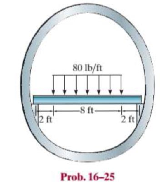
Chapter 16.2, Problem 25P
The floor beam of the airplane is subjected to the loading shown. Assuming that the fuselage exerts only vertical reactions on the ends of the beam, determine the maximum deflection of the beam. EI is constant.
Expert Solution & Answer
Want to see the full answer?
Check out a sample textbook solution
Students have asked these similar questions
what is shear stress and normal? how to tell them while calculating?
12 mm
45 mm
20 kN
20 kN
12 mm
45 mm
PROBLEM 1.61
For the assembly and loading of Problem 1.60, determine (a) the
average shearing stress in the pin at C, (b) the average bearing stress at
C in member BC, (c) the average bearing stress at B in member BC.
PROBLEM 1.60 Two horizontal 20-kN forces are applied to pin B of
the assembly shown. Knowing that a pin of 20-mm diameter is used at
each connection, determine the maximum value of the average normal
stress (a) in link AB, (b) in link BC.
How do you find these answers?
Chapter 16 Solutions
Statics and Mechanics of Materials Plus Mastering Engineering with Pearson eText - Access Card Package (5th Edition)
Ch. 16.2 - In each ease, determine the internal bending...Ch. 16.2 - Prob. 1FPCh. 16.2 - Determine the slope and deflection of end A of the...Ch. 16.2 - Prob. 3FPCh. 16.2 - Prob. 4FPCh. 16.2 - Determine the maximum deflection of the simply...Ch. 16.2 - Prob. 6FPCh. 16.2 - An L2 steel strap having a thickness of 0.125 in....Ch. 16.2 - The L2 steel blade of the band saw wraps around...Ch. 16.2 - A picture is taken of a man performing a pole...
Ch. 16.2 - Determine the equation of the elastic curve for...Ch. 16.2 - Determine the deflection of end C of the...Ch. 16.2 - Prob. 6PCh. 16.2 - The A-36 steel beam has a depth of 10 in. and is...Ch. 16.2 - Prob. 8PCh. 16.2 - Determine the equations of the elastic curve for...Ch. 16.2 - Determine the equations of the elastic curve using...Ch. 16.2 - Determine the equations of the elastic curve using...Ch. 16.2 - Prob. 12PCh. 16.2 - Determine the maximum deflection of the beam and...Ch. 16.2 - The simply supported shaft has a moment of inertia...Ch. 16.2 - A torque wrench is used to tighten the nut on a...Ch. 16.2 - The pipe can be assumed roller supported at its...Ch. 16.2 - Determine the equations of the elastic curve for...Ch. 16.2 - The bar is supported by a roller constraint at B,...Ch. 16.2 - The bar is supported by a roller constraint at B,...Ch. 16.2 - Determine the equations of the elastic curve using...Ch. 16.2 - Prob. 21PCh. 16.2 - Determine the elastic curve for the cantilevered...Ch. 16.2 - Prob. 23PCh. 16.2 - Prob. 24PCh. 16.2 - The floor beam of the airplane is subjected to the...Ch. 16.2 - Determine the maximum deflection of the simply...Ch. 16.2 - The beam is made of a material having a specific...Ch. 16.2 - Determine the slope at end B and the maximum...Ch. 16.2 - Prob. 29PCh. 16.2 - Determine the equations of the elastic curve using...Ch. 16.3 - The shaft is supported at A by a journal bearing...Ch. 16.3 - The shaft supports the two pulley loads shown....Ch. 16.3 - Prob. 33PCh. 16.3 - Prob. 34PCh. 16.3 - The beam is subjected to the load shown. Determine...Ch. 16.3 - Prob. 36PCh. 16.3 - Determine the equation of the elastic curve and...Ch. 16.3 - Prob. 38PCh. 16.3 - Prob. 39PCh. 16.3 - Determine the slope at A and the deflection of end...Ch. 16.3 - Determine the maximum deflection in region AB of...Ch. 16.3 - Prob. 42PCh. 16.3 - Prob. 43PCh. 16.3 - Prob. 44PCh. 16.4 - The W10 15 cantilevered beam is made of A-36...Ch. 16.4 - The W10 15 cantilevered beam is made of A-36...Ch. 16.4 - The W14 43 simply supported beam is made of A992...Ch. 16.4 - The W14 43 simply supported beam is made of A992...Ch. 16.4 - The W14 43 simply supported beam is made of A-36...Ch. 16.4 - The W14 43 simply supported beam is made of A-36...Ch. 16.4 - The W8 48 cantilevered beam is made of A-36 steel...Ch. 16.4 - The beam supports the loading shown. Code...Ch. 16.4 - Prob. 53PCh. 16.4 - The W8 48 cantilevered beam is made of A-36 steel...Ch. 16.4 - Prob. 55PCh. 16.4 - Prob. 56PCh. 16.4 - Prob. 57PCh. 16.4 - The assembly consists of a cantilevered beam CB...Ch. 16.4 - Prob. 59PCh. 16.4 - Prob. 60PCh. 16.5 - Determine the reactions at the fixed support A and...Ch. 16.5 - Prob. 8FPCh. 16.5 - Determine the reactions at the fixed support A and...Ch. 16.5 - Prob. 10FPCh. 16.5 - Prob. 11FPCh. 16.5 - Prob. 12FPCh. 16.5 - Prob. 61PCh. 16.5 - Determine the reactions at the supports, then draw...Ch. 16.5 - Determine the reactions at the supports, then draw...Ch. 16.5 - Prob. 64PCh. 16.5 - The beam is used to support the 20-kip load....Ch. 16.5 - Prob. 66PCh. 16.5 - Determine the reactions at the supports A and B....Ch. 16.5 - Before the uniform distributed load is applied to...Ch. 16.5 - Prob. 69PCh. 16.5 - Prob. 70PCh. 16.5 - The beam is supported by the bolted supports at...Ch. 16.5 - Prob. 72PCh. 16.5 - Prob. 73PCh. 16 - Prob. 1RPCh. 16 - Draw the bending-moment diagram for the shaft and...Ch. 16 - Prob. 3RPCh. 16 - Determine the equations of the elastic curve for...Ch. 16 - Determine the maximum deflection between the...Ch. 16 - Prob. 6RPCh. 16 - The framework consists of two A-36 steel...Ch. 16 - Prob. 8RPCh. 16 - Using the method of superposition, determine the...
Knowledge Booster


Learn more about
Need a deep-dive on the concept behind this application? Look no further. Learn more about this topic, mechanical-engineering and related others by exploring similar questions and additional content below.Similar questions
- 250 mm 400 mm A B C E F 250 mm PROBLEM 1.52 Each of the two vertical links CF connecting the two horizontal members AD and EG has a 10 × 40-mm uniform rectangular cross section and is made of a steel with an ultimate strength in tension of 400 MPa, while each of the pins at C and F has a 20-mm diameter and are made of a steel with an ultimate strength in shear of 150 MPa. Determine the overall factor of safety for the links CF and the pins connecting them to the horizontal members. 24 kNarrow_forward50 mm 12 mm B O C OA 300 mm 450 mm E PROBLEM 1.51 Each of the steel links AB and CD is connected to a support and to member BCE by 25-mm-diameter steel pins acting in single shear. Knowing that the ultimate shearing stress is 210 MPa for the steel used in the pins and that the ultimate normal stress is 490 MPa for the steel used in the links, determine the allowable load P if an overall factor of safety of 3.0 is desired. (Note that the links are not reinforced around the pin holes.)arrow_forward3. A 15% magnesium chloride solution is flowing through a 5-nom sch 40 commercial steel pipe at a rate of 325,000 lbm/h. The average temperature of the magnesium chloride solution as it flows through the pipe is 10°F. Determine the convective heat transfer coefficient inside the pipe.arrow_forward
- 2. Jojoba oil is flowing through a ¾-nom stainless steel pipe at a flow rate of 1,850 lbm/h. After the velocity profile in the pipe is fully developed, the oil enters a heater, as shown in Figure P5.7. The length of the heater section is 5 ft. The properties of the jojoba oil at the average temperature in the heater section are given in Table P5.7. Determine the convective heat transfer coefficient inside the heater section of the pipe. ¾ nom stainless steel pipe Heater section L=5ft Fig. P5.7 TABLE P5.7 Thermophysical Properties of Jojoba Oil at the Average Temperature in the Heater P (lbm/ft³) 68.671 (Btu/lbm-R) 0.30339 μ (lbm/ft-s) 0.012095 k (Btu/h-ft-°F) 0.077424arrow_forward1. Water is flowing inside of a 3-std type K copper tube at a flow rate of 1.2 kg/s. The average temperature of the water is 50°C. Cold, dry air at a temperature of 5°C and atmospheric pressure flows outside of the tube in cross flow with a velocity of 85 m/s. Determine the UA product for this tube under clean conditions.arrow_forwardHints: Find the closed loop transfer function and then plot the step response for diFerentvalues of K in MATLAB. Show step response plot for different values of K. Auto Controls Show solutions and provide matlab code NO COPIED ANSWERS OR WILL REPORT!!!!arrow_forward
- 37. The vertical shaft shown in Figure P12-37 is driven at a speed of 600 rpm with 4.0 hp entering through the bevel gear. Each of the two chain sprockets delivers 2.0 hp to the side to drive mixer blades in a chemical reactor vessel. The bevel gear has a diametral pitch of 5, a pitch diameter of 9.000 in, a face width of 1.31 in, and a pressure angle of 20°. Use SAE 4140 OQT 1000 steel for the shaft. See Chapter 10 for the methods for computing the forces on the bevel gear. Figure P12-37: P37-Bevel gear drive with two chain sprockets Each problem includes the following details: ■Design the complete shaft, including the specification of the overall geometry and the consideration of stress con- centration factors. The analysis would show the minimum acceptable diameter at each point on the shaft to be safe from the standpoint of strength. Homework Problems 12-24, 12-35, and 12-37 from textbook, done in spreadsheet form. Place drawings of the load, shear, and bending moment body diagrams…arrow_forward35. The double-reduction, helical gear reducer shown in Figure P12-35 transmits 5.0 hp. Shaft 1 is the input, rotating at 1800 rpm and receiving power directly from an electric motor through a flexible coupling. Shaft 2 rotates at 900 rpm. Shaft 3 is the output, rotating at 300 rpm. A chain sprocket is mounted on the output shaft as shown and delivers the power upward. The data for the gears are given in Table 12-5. Each gear has a 1412° normal pressure angle and a 45° helix angle. The combinations of left- and right-hand helixes are arranged so that the axial forces oppose each other on shaft 2 as shown. Use SAE 4140 OQT 1200 for the shafts. Figure P12-35: P35-Double-reduction helical drive Each problem includes the following details: ■Design the complete shaft, including the specification of the overall geometry and the consideration of stress con- centration factors. The analysis would show the minimum acceptable diameter at each point on the shaft to be safe from the standpoint of…arrow_forwardConsider 0.65 kg of N2 at 300 K, 1 bar contained in a rigid tank connected by a valve to another rigid tank holding 0.3 kg of CO2 at 300 K, 1 bar. The valve is opened and gases are allowed to mix, achieving an equilibrium state at 290 K. Determine: (a) the volume of each tank, in m³. (b) the final pressure, in bar. (c) the magnitude of the heat transfer to or from the gases during the process, in kJ. (d) the entropy change of each gas and of the overall system, in kJ/K.arrow_forward
- Bài 1. Cho cơ hệ như hình 1. Hình biểu diễn lược đổ cơ hệ tại vị trí cân bằng tĩnh. Trục tọa độ Oy hướng theo phương chuyển động của vật 1, gốc O đặt tại vị trí cân bằng của vật 1(tức khi lò xo biến dạng tĩnh). Bỏ qua khối lượng của thanh số 3. Vật rắn 2 là pulley 2 tầng đồng chất có bán kính ngoài 21, bán kính trong I, bán kính quán tính đối với trục qua tâm P-1.5, khối lượng m:. Vật rắn 4 là thanh thắng đồng chất có khối lượng m, chiều dài 1. Cho các số liệu: m = 2kg, m= = 5kg, m = 4kg, k=40(N/cm), ! – 0.8(m),r=0.1(m). Điều kiện đầu y; =0.5 cm );j = 10 cm/s) . Giả sử hệ dao động bé, Vật rắn 2 chuyển động lăn không trượt trên mặt phẳng ngang. 1. Viết phương trình chuyển động của hệ. 2. Xác định tần số dao động tự do của hệ. 3. Xác định đáp ứng dao động tự do của hệ. dây dây 1 2r Hình 1 y 3 -2 I k www. -2arrow_forwardHints: Find the closed loop transfer function and then plot the step response for diFerentvalues of K in MATLAB. Show step response plot for different values of K. Auto Controls Show solutions and provide matlab code NO COPIED ANSWERS OR WILL REPORTarrow_forwardObtain the response of the system shown below for a parabolic or acceleration input r(t);where Auto Controls Show full solutionarrow_forward
arrow_back_ios
SEE MORE QUESTIONS
arrow_forward_ios
Recommended textbooks for you
 Elements Of ElectromagneticsMechanical EngineeringISBN:9780190698614Author:Sadiku, Matthew N. O.Publisher:Oxford University Press
 Mechanics of Materials (10th Edition)Mechanical EngineeringISBN:9780134319650Author:Russell C. HibbelerPublisher:PEARSON
 Thermodynamics: An Engineering ApproachMechanical EngineeringISBN:9781259822674Author:Yunus A. Cengel Dr., Michael A. BolesPublisher:McGraw-Hill Education
 Control Systems EngineeringMechanical EngineeringISBN:9781118170519Author:Norman S. NisePublisher:WILEY
 Mechanics of Materials (MindTap Course List)Mechanical EngineeringISBN:9781337093347Author:Barry J. Goodno, James M. GerePublisher:Cengage Learning
 Engineering Mechanics: StaticsMechanical EngineeringISBN:9781118807330Author:James L. Meriam, L. G. Kraige, J. N. BoltonPublisher:WILEY
Elements Of Electromagnetics
Mechanical Engineering
ISBN:9780190698614
Author:Sadiku, Matthew N. O.
Publisher:Oxford University Press
Mechanics of Materials (10th Edition)
Mechanical Engineering
ISBN:9780134319650
Author:Russell C. Hibbeler
Publisher:PEARSON
Thermodynamics: An Engineering Approach
Mechanical Engineering
ISBN:9781259822674
Author:Yunus A. Cengel Dr., Michael A. Boles
Publisher:McGraw-Hill Education
Control Systems Engineering
Mechanical Engineering
ISBN:9781118170519
Author:Norman S. Nise
Publisher:WILEY
Mechanics of Materials (MindTap Course List)
Mechanical Engineering
ISBN:9781337093347
Author:Barry J. Goodno, James M. Gere
Publisher:Cengage Learning
Engineering Mechanics: Statics
Mechanical Engineering
ISBN:9781118807330
Author:James L. Meriam, L. G. Kraige, J. N. Bolton
Publisher:WILEY
Solids: Lesson 53 - Slope and Deflection of Beams Intro; Author: Jeff Hanson;https://www.youtube.com/watch?v=I7lTq68JRmY;License: Standard YouTube License, CC-BY