
Statics and Mechanics of Materials Plus Mastering Engineering with Pearson eText - Access Card Package (5th Edition)
5th Edition
ISBN: 9780134301006
Author: Russell C. Hibbeler
Publisher: PEARSON
expand_more
expand_more
format_list_bulleted
Concept explainers
Videos
Textbook Question
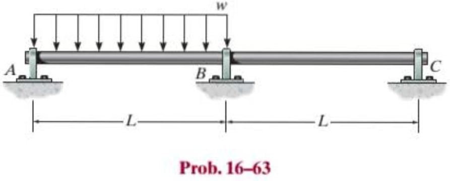
Chapter 16.5, Problem 63P
Determine the reactions at the supports, then draw the shear and moment diagrams. EI is constant.
Expert Solution & Answer
Want to see the full answer?
Check out a sample textbook solution
Students have asked these similar questions
A 7.25-hp (shaft) pump is used to raise water to an elevation of 17 m. If the mechanical efficiencyof the pump is 84 percent, determine the maximum volume flow rate of water.
Consider a double-fluid manometer attached to an air pipe shown below. If the specific gravity ofone fluid is 13.8, determine the specific gravity of the other fluid for the indicated absolutepressure of air. Take the atmospheric pressure to be 95 kPa
A race car enters the circular portion of a track that has a radius of 65 m. Disregard the 70 m in the picture. When the car enters the curve at point P, it is traveling with a speed of 120 km/h that is increasing at 5 m/s^2 . Three seconds later, determine the x and y components of velocity and acceleration of the car. I'm having trouble getting the correct y component of acceleration. all the other answers are correct. thank you!
Chapter 16 Solutions
Statics and Mechanics of Materials Plus Mastering Engineering with Pearson eText - Access Card Package (5th Edition)
Ch. 16.2 - In each ease, determine the internal bending...Ch. 16.2 - Prob. 1FPCh. 16.2 - Determine the slope and deflection of end A of the...Ch. 16.2 - Prob. 3FPCh. 16.2 - Prob. 4FPCh. 16.2 - Determine the maximum deflection of the simply...Ch. 16.2 - Prob. 6FPCh. 16.2 - An L2 steel strap having a thickness of 0.125 in....Ch. 16.2 - The L2 steel blade of the band saw wraps around...Ch. 16.2 - A picture is taken of a man performing a pole...
Ch. 16.2 - Determine the equation of the elastic curve for...Ch. 16.2 - Determine the deflection of end C of the...Ch. 16.2 - Prob. 6PCh. 16.2 - The A-36 steel beam has a depth of 10 in. and is...Ch. 16.2 - Prob. 8PCh. 16.2 - Determine the equations of the elastic curve for...Ch. 16.2 - Determine the equations of the elastic curve using...Ch. 16.2 - Determine the equations of the elastic curve using...Ch. 16.2 - Prob. 12PCh. 16.2 - Determine the maximum deflection of the beam and...Ch. 16.2 - The simply supported shaft has a moment of inertia...Ch. 16.2 - A torque wrench is used to tighten the nut on a...Ch. 16.2 - The pipe can be assumed roller supported at its...Ch. 16.2 - Determine the equations of the elastic curve for...Ch. 16.2 - The bar is supported by a roller constraint at B,...Ch. 16.2 - The bar is supported by a roller constraint at B,...Ch. 16.2 - Determine the equations of the elastic curve using...Ch. 16.2 - Prob. 21PCh. 16.2 - Determine the elastic curve for the cantilevered...Ch. 16.2 - Prob. 23PCh. 16.2 - Prob. 24PCh. 16.2 - The floor beam of the airplane is subjected to the...Ch. 16.2 - Determine the maximum deflection of the simply...Ch. 16.2 - The beam is made of a material having a specific...Ch. 16.2 - Determine the slope at end B and the maximum...Ch. 16.2 - Prob. 29PCh. 16.2 - Determine the equations of the elastic curve using...Ch. 16.3 - The shaft is supported at A by a journal bearing...Ch. 16.3 - The shaft supports the two pulley loads shown....Ch. 16.3 - Prob. 33PCh. 16.3 - Prob. 34PCh. 16.3 - The beam is subjected to the load shown. Determine...Ch. 16.3 - Prob. 36PCh. 16.3 - Determine the equation of the elastic curve and...Ch. 16.3 - Prob. 38PCh. 16.3 - Prob. 39PCh. 16.3 - Determine the slope at A and the deflection of end...Ch. 16.3 - Determine the maximum deflection in region AB of...Ch. 16.3 - Prob. 42PCh. 16.3 - Prob. 43PCh. 16.3 - Prob. 44PCh. 16.4 - The W10 15 cantilevered beam is made of A-36...Ch. 16.4 - The W10 15 cantilevered beam is made of A-36...Ch. 16.4 - The W14 43 simply supported beam is made of A992...Ch. 16.4 - The W14 43 simply supported beam is made of A992...Ch. 16.4 - The W14 43 simply supported beam is made of A-36...Ch. 16.4 - The W14 43 simply supported beam is made of A-36...Ch. 16.4 - The W8 48 cantilevered beam is made of A-36 steel...Ch. 16.4 - The beam supports the loading shown. Code...Ch. 16.4 - Prob. 53PCh. 16.4 - The W8 48 cantilevered beam is made of A-36 steel...Ch. 16.4 - Prob. 55PCh. 16.4 - Prob. 56PCh. 16.4 - Prob. 57PCh. 16.4 - The assembly consists of a cantilevered beam CB...Ch. 16.4 - Prob. 59PCh. 16.4 - Prob. 60PCh. 16.5 - Determine the reactions at the fixed support A and...Ch. 16.5 - Prob. 8FPCh. 16.5 - Determine the reactions at the fixed support A and...Ch. 16.5 - Prob. 10FPCh. 16.5 - Prob. 11FPCh. 16.5 - Prob. 12FPCh. 16.5 - Prob. 61PCh. 16.5 - Determine the reactions at the supports, then draw...Ch. 16.5 - Determine the reactions at the supports, then draw...Ch. 16.5 - Prob. 64PCh. 16.5 - The beam is used to support the 20-kip load....Ch. 16.5 - Prob. 66PCh. 16.5 - Determine the reactions at the supports A and B....Ch. 16.5 - Before the uniform distributed load is applied to...Ch. 16.5 - Prob. 69PCh. 16.5 - Prob. 70PCh. 16.5 - The beam is supported by the bolted supports at...Ch. 16.5 - Prob. 72PCh. 16.5 - Prob. 73PCh. 16 - Prob. 1RPCh. 16 - Draw the bending-moment diagram for the shaft and...Ch. 16 - Prob. 3RPCh. 16 - Determine the equations of the elastic curve for...Ch. 16 - Determine the maximum deflection between the...Ch. 16 - Prob. 6RPCh. 16 - The framework consists of two A-36 steel...Ch. 16 - Prob. 8RPCh. 16 - Using the method of superposition, determine the...
Knowledge Booster


Learn more about
Need a deep-dive on the concept behind this application? Look no further. Learn more about this topic, mechanical-engineering and related others by exploring similar questions and additional content below.Similar questions
- Figure: 06_P041 Copyright 2013 Pearson Education, publishing a Prentice Hall 2. Determine the force that the jaws J of the metal cutters exert on the smooth cable C if 100-N forces are applied to the handles. The jaws are pinned at E and A, and D and B. There is also a pin at F. 400 mm 15° 20 mm A 15° 15 D B 30 mm² 80 mm 20 mm 400 mm Figure: 06_P090 Copyright 2013 Pearson Education, publishing as Prentice Hall 15° 100 N 100 N 15°arrow_forwardA telemetry system is used to quantify kinematic values of a ski jumper immediately before the jumper leaves the ramp. According to the system r=560 ft , r˙=−105 ft/s , r¨=−10 ft/s2 , θ=25° , θ˙=0.07 rad/s , θ¨=0.06 rad/s2 Determine the velocity of the skier immediately before leaving the jump. The velocity of the skier immediately before leaving the jump along with its direction is ? I have 112.08 ft/s but can't seem to get the direction correct. Determine the acceleration of the skier at this instant. At this instant, the acceleration of the skier along with its direction is ? acceleration is 22.8 ft/s^2 but need help with direction. Need help with velocity direction and acceleration direction please.arrow_forwardFor Problems 18-22 (Table 7-27), design a V-belt drive. Specify the belt size, the sheave sizes, the number of belts, the actual output speed, and the center distance.arrow_forward
- only 21arrow_forwardonly 41arrow_forwardNormal and tangential components-relate to x-y coordinates A race car enters the circular portion of a track that has a radius of 65 m. When the car enters the curve at point P, it is traveling with a speed of 120 km/h that is increasing at 5 m/s^2 . Three seconds later, determine the x and y components of velocity and acceleration of the car. I need help with finding the y component of the total acceleration. I had put -32 but its incorrect. but i keep getting figures around that numberarrow_forward
- The bracket BCD is hinged at C and attached to a control cable at B. Let F₁ = 275 N and F2 = 275 N. F1 B a=0.18 m C A 0.4 m -0.4 m- 0.24 m Determine the reaction at C. The reaction at C N Z F2 Darrow_forwardConsider the angle bar shown in the given figure A W 240 mm B 80 mm Draw the free-body diagram needed to determine the reactions at A and B when a = 150 mm. This problem could also be approached as a 3-force body using method of Section 4.2B.arrow_forwardA telemetry system is used to quantify kinematic values of a ski jumper immediately before the jumper leaves the ramp. According to the system r=560 ft , r˙=−105 ft/s , r¨=−10 ft/s2 , θ=25° , θ˙=0.07 rad/s , θ¨=0.06 rad/s2 Determine the velocity of the skier immediately before leaving the jump. The velocity of the skier immediately before leaving the jump along with its direction is ? I have 112.08 ft/s but can't seem to get the direction correct. Determine the acceleration of the skier at this instant. At this instant, the acceleration of the skier along with its direction is ? acceleration is 22.8 ft/s^2 but need help with direction. Need help with velocity direction and acceleration direction please.arrow_forward
- For the stop bracket shown, locate the x coordinate of the center of gravity. Consider a = = 16.50 mm. 34 mm 62 mm 51 mm 10 mm 100 mm 88 mm 55 mm 45 mm The x coordinate of the center of gravity is mm.arrow_forwardIn the given figure, the bent rod ABEF is supported by bearings at C and D and by wire AH. The portion AB of the rod is 250 mm long, and the load W is 580 N. Assume that the bearing at D does not exert any axial thrust. H B A с 30° 250 mm D Z 50 mm 300 mm F 250 mm 50 mm W Draw the free-body diagram needed to determine the tension in wire AH and the reactions at C and D.arrow_forwardA 10-ft boom is acted upon by the 810-lb force as shown in the figure. D 6 ft 6 ft E B 7 ft C 6 ft x 4 ft W Draw the free-body diagram needed to determine the tension in each cable and the reaction at the ball-and-socket joint at A.arrow_forward
arrow_back_ios
SEE MORE QUESTIONS
arrow_forward_ios
Recommended textbooks for you
 Elements Of ElectromagneticsMechanical EngineeringISBN:9780190698614Author:Sadiku, Matthew N. O.Publisher:Oxford University Press
 Mechanics of Materials (10th Edition)Mechanical EngineeringISBN:9780134319650Author:Russell C. HibbelerPublisher:PEARSON
 Thermodynamics: An Engineering ApproachMechanical EngineeringISBN:9781259822674Author:Yunus A. Cengel Dr., Michael A. BolesPublisher:McGraw-Hill Education
 Control Systems EngineeringMechanical EngineeringISBN:9781118170519Author:Norman S. NisePublisher:WILEY
 Mechanics of Materials (MindTap Course List)Mechanical EngineeringISBN:9781337093347Author:Barry J. Goodno, James M. GerePublisher:Cengage Learning
 Engineering Mechanics: StaticsMechanical EngineeringISBN:9781118807330Author:James L. Meriam, L. G. Kraige, J. N. BoltonPublisher:WILEY
Elements Of Electromagnetics
Mechanical Engineering
ISBN:9780190698614
Author:Sadiku, Matthew N. O.
Publisher:Oxford University Press
Mechanics of Materials (10th Edition)
Mechanical Engineering
ISBN:9780134319650
Author:Russell C. Hibbeler
Publisher:PEARSON
Thermodynamics: An Engineering Approach
Mechanical Engineering
ISBN:9781259822674
Author:Yunus A. Cengel Dr., Michael A. Boles
Publisher:McGraw-Hill Education
Control Systems Engineering
Mechanical Engineering
ISBN:9781118170519
Author:Norman S. Nise
Publisher:WILEY
Mechanics of Materials (MindTap Course List)
Mechanical Engineering
ISBN:9781337093347
Author:Barry J. Goodno, James M. Gere
Publisher:Cengage Learning
Engineering Mechanics: Statics
Mechanical Engineering
ISBN:9781118807330
Author:James L. Meriam, L. G. Kraige, J. N. Bolton
Publisher:WILEY
Understanding Shear Force and Bending Moment Diagrams; Author: The Efficient Engineer;https://www.youtube.com/watch?v=C-FEVzI8oe8;License: Standard YouTube License, CC-BY
Bending Stress; Author: moodlemech;https://www.youtube.com/watch?v=9QIqewkE6xM;License: Standard Youtube License