
Statics and Mechanics of Materials Plus Mastering Engineering with Pearson eText - Access Card Package (5th Edition)
5th Edition
ISBN: 9780134301006
Author: Russell C. Hibbeler
Publisher: PEARSON
expand_more
expand_more
format_list_bulleted
Concept explainers
Videos
Textbook Question
Chapter 16.2, Problem 19P
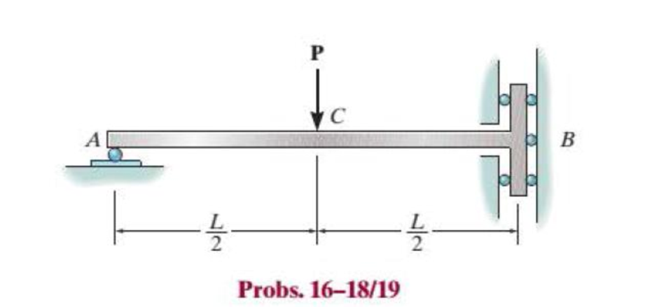
The bar is supported by a roller constraint at B, which allows vertical displacement but resists axial load and moment. If the bar is subjected to the loading shown, determine the slope at A and the deflection at C. EI is constant.
16–19. Determine the deflection at B of the bar in Prob. 16–18.
Expert Solution & Answer
Want to see the full answer?
Check out a sample textbook solution
Students have asked these similar questions
I am not able to solve this question. Each part doesn't make sense to me.
Exercises
Find the solution of the following Differential Equations
1) y" + y = 3x²
3)
"+2y+3y=27x
5) y"+y=6sin(x)
7) y"+4y+4y = 18 cosh(x)
9) (4)-5y"+4y = 10 cos(x)
11) y"+y=x²+x
13) y"-2y+y=e*
15) y+2y"-y'-2y=1-4x³
2) y"+2y' + y = x²
4) "+y=-30 sin(4x)
6) y"+4y+3y=sin(x)+2 cos(x)
8) y"-2y+2y= 2e* cos(x)
10) y+y-2y=3e*
12) y"-y=e*
14) y"+y+y=x+4x³ +12x²
16) y"-2y+2y=2e* cos(x)
Qu. 15 What are the indices for the Plane 1 drawn in the following sketch?
Qu. 16 What are the Miller indices for the Plane shown in the following cubic unit cell?
this is material engineering please show all work
Chapter 16 Solutions
Statics and Mechanics of Materials Plus Mastering Engineering with Pearson eText - Access Card Package (5th Edition)
Ch. 16.2 - In each ease, determine the internal bending...Ch. 16.2 - Prob. 1FPCh. 16.2 - Determine the slope and deflection of end A of the...Ch. 16.2 - Prob. 3FPCh. 16.2 - Prob. 4FPCh. 16.2 - Determine the maximum deflection of the simply...Ch. 16.2 - Prob. 6FPCh. 16.2 - An L2 steel strap having a thickness of 0.125 in....Ch. 16.2 - The L2 steel blade of the band saw wraps around...Ch. 16.2 - A picture is taken of a man performing a pole...
Ch. 16.2 - Determine the equation of the elastic curve for...Ch. 16.2 - Determine the deflection of end C of the...Ch. 16.2 - Prob. 6PCh. 16.2 - The A-36 steel beam has a depth of 10 in. and is...Ch. 16.2 - Prob. 8PCh. 16.2 - Determine the equations of the elastic curve for...Ch. 16.2 - Determine the equations of the elastic curve using...Ch. 16.2 - Determine the equations of the elastic curve using...Ch. 16.2 - Prob. 12PCh. 16.2 - Determine the maximum deflection of the beam and...Ch. 16.2 - The simply supported shaft has a moment of inertia...Ch. 16.2 - A torque wrench is used to tighten the nut on a...Ch. 16.2 - The pipe can be assumed roller supported at its...Ch. 16.2 - Determine the equations of the elastic curve for...Ch. 16.2 - The bar is supported by a roller constraint at B,...Ch. 16.2 - The bar is supported by a roller constraint at B,...Ch. 16.2 - Determine the equations of the elastic curve using...Ch. 16.2 - Prob. 21PCh. 16.2 - Determine the elastic curve for the cantilevered...Ch. 16.2 - Prob. 23PCh. 16.2 - Prob. 24PCh. 16.2 - The floor beam of the airplane is subjected to the...Ch. 16.2 - Determine the maximum deflection of the simply...Ch. 16.2 - The beam is made of a material having a specific...Ch. 16.2 - Determine the slope at end B and the maximum...Ch. 16.2 - Prob. 29PCh. 16.2 - Determine the equations of the elastic curve using...Ch. 16.3 - The shaft is supported at A by a journal bearing...Ch. 16.3 - The shaft supports the two pulley loads shown....Ch. 16.3 - Prob. 33PCh. 16.3 - Prob. 34PCh. 16.3 - The beam is subjected to the load shown. Determine...Ch. 16.3 - Prob. 36PCh. 16.3 - Determine the equation of the elastic curve and...Ch. 16.3 - Prob. 38PCh. 16.3 - Prob. 39PCh. 16.3 - Determine the slope at A and the deflection of end...Ch. 16.3 - Determine the maximum deflection in region AB of...Ch. 16.3 - Prob. 42PCh. 16.3 - Prob. 43PCh. 16.3 - Prob. 44PCh. 16.4 - The W10 15 cantilevered beam is made of A-36...Ch. 16.4 - The W10 15 cantilevered beam is made of A-36...Ch. 16.4 - The W14 43 simply supported beam is made of A992...Ch. 16.4 - The W14 43 simply supported beam is made of A992...Ch. 16.4 - The W14 43 simply supported beam is made of A-36...Ch. 16.4 - The W14 43 simply supported beam is made of A-36...Ch. 16.4 - The W8 48 cantilevered beam is made of A-36 steel...Ch. 16.4 - The beam supports the loading shown. Code...Ch. 16.4 - Prob. 53PCh. 16.4 - The W8 48 cantilevered beam is made of A-36 steel...Ch. 16.4 - Prob. 55PCh. 16.4 - Prob. 56PCh. 16.4 - Prob. 57PCh. 16.4 - The assembly consists of a cantilevered beam CB...Ch. 16.4 - Prob. 59PCh. 16.4 - Prob. 60PCh. 16.5 - Determine the reactions at the fixed support A and...Ch. 16.5 - Prob. 8FPCh. 16.5 - Determine the reactions at the fixed support A and...Ch. 16.5 - Prob. 10FPCh. 16.5 - Prob. 11FPCh. 16.5 - Prob. 12FPCh. 16.5 - Prob. 61PCh. 16.5 - Determine the reactions at the supports, then draw...Ch. 16.5 - Determine the reactions at the supports, then draw...Ch. 16.5 - Prob. 64PCh. 16.5 - The beam is used to support the 20-kip load....Ch. 16.5 - Prob. 66PCh. 16.5 - Determine the reactions at the supports A and B....Ch. 16.5 - Before the uniform distributed load is applied to...Ch. 16.5 - Prob. 69PCh. 16.5 - Prob. 70PCh. 16.5 - The beam is supported by the bolted supports at...Ch. 16.5 - Prob. 72PCh. 16.5 - Prob. 73PCh. 16 - Prob. 1RPCh. 16 - Draw the bending-moment diagram for the shaft and...Ch. 16 - Prob. 3RPCh. 16 - Determine the equations of the elastic curve for...Ch. 16 - Determine the maximum deflection between the...Ch. 16 - Prob. 6RPCh. 16 - The framework consists of two A-36 steel...Ch. 16 - Prob. 8RPCh. 16 - Using the method of superposition, determine the...
Knowledge Booster


Learn more about
Need a deep-dive on the concept behind this application? Look no further. Learn more about this topic, mechanical-engineering and related others by exploring similar questions and additional content below.Similar questions
- Qu. 13 What are the indices for the Direction 2 indicated by vector in the following sketch? Qu. 14 Determine the indices for the direction A and B shown in the following cubic unit cell. please show all work step by step from material engineeringarrow_forwardThe thin-walled open cross section shown is transmitting torque 7. The angle of twist ₁ per unit length of each leg can be determined separately using the equation 01 = 3Ti GLIC 3 where G is the shear modulus, ₁ is the angle of twist per unit length, T is torque, and L is the length of the median line. In this case, i = 1, 2, 3, and T; represents the torque in leg i. Assuming that the angle of twist per unit length for each leg is the same, show that T= Lic³ and Tmaz = G01 Cmax Consider a steel section with Tallow = 12.40 kpsi. C1 2 mm L1 20 mm C2 3 mm L2 30 mm C3 2 mm L3 25 mm Determine the torque transmitted by each leg and the torque transmitted by the entire section. The torque transmitted by the first leg is | N-m. The torque transmitted by the second leg is N-m. The torque transmitted by the third leg is N-m. The torque transmitted by the entire section is N-m.arrow_forwardPlease help, make sure it's to box out and make it clear what answers go where...arrow_forward
arrow_back_ios
SEE MORE QUESTIONS
arrow_forward_ios
Recommended textbooks for you
 Elements Of ElectromagneticsMechanical EngineeringISBN:9780190698614Author:Sadiku, Matthew N. O.Publisher:Oxford University Press
 Mechanics of Materials (10th Edition)Mechanical EngineeringISBN:9780134319650Author:Russell C. HibbelerPublisher:PEARSON
 Thermodynamics: An Engineering ApproachMechanical EngineeringISBN:9781259822674Author:Yunus A. Cengel Dr., Michael A. BolesPublisher:McGraw-Hill Education
 Control Systems EngineeringMechanical EngineeringISBN:9781118170519Author:Norman S. NisePublisher:WILEY
 Mechanics of Materials (MindTap Course List)Mechanical EngineeringISBN:9781337093347Author:Barry J. Goodno, James M. GerePublisher:Cengage Learning
 Engineering Mechanics: StaticsMechanical EngineeringISBN:9781118807330Author:James L. Meriam, L. G. Kraige, J. N. BoltonPublisher:WILEY
Elements Of Electromagnetics
Mechanical Engineering
ISBN:9780190698614
Author:Sadiku, Matthew N. O.
Publisher:Oxford University Press
Mechanics of Materials (10th Edition)
Mechanical Engineering
ISBN:9780134319650
Author:Russell C. Hibbeler
Publisher:PEARSON
Thermodynamics: An Engineering Approach
Mechanical Engineering
ISBN:9781259822674
Author:Yunus A. Cengel Dr., Michael A. Boles
Publisher:McGraw-Hill Education
Control Systems Engineering
Mechanical Engineering
ISBN:9781118170519
Author:Norman S. Nise
Publisher:WILEY
Mechanics of Materials (MindTap Course List)
Mechanical Engineering
ISBN:9781337093347
Author:Barry J. Goodno, James M. Gere
Publisher:Cengage Learning
Engineering Mechanics: Statics
Mechanical Engineering
ISBN:9781118807330
Author:James L. Meriam, L. G. Kraige, J. N. Bolton
Publisher:WILEY
Solids: Lesson 53 - Slope and Deflection of Beams Intro; Author: Jeff Hanson;https://www.youtube.com/watch?v=I7lTq68JRmY;License: Standard YouTube License, CC-BY