
Concept explainers
Videos
The 6-kg rod BC connects a 10-kg disk centered at A to a 5-kg rod CD. The motion of the system is controlled by the couple M applied to disk A. Knowing that at the instant shown disk A has an angular velocity of 36 rad/s clockwise and no angular acceleration, determine (a) the couple M, (b) the components of the force exerted at C on rod BC.
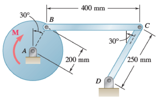
Fig. P16.135 and P16.136
(a)
Find the couple M.
Answer to Problem 16.135P
The couple M is
Explanation of Solution
Given information:
The mass of the rod BC is
The mass of the disk is
The mass of the rod CD is
The angular velocity is
The angular acceleration is
Calculation:
Consider the acceleration due to gravity as
Calculate the velocity of disk AB
Substitute
Calculate the velocity of rod BC
The velocity of disk AB is equal to the velocity of rod BC.
Substitute
Calculate the angular velocity of rod CD
Substitute
Apply the acceleration analysis as shown below.
Calculate the acceleration for disk AB
Substitute
Calculate the acceleration for rod BC
Substitute
Calculate the acceleration for rod CD
Substitute
Equating the components of Equations (1) and (2) as shown below.
Along x component.
Along y component.
Substitute
Calculate the acceleration of the mass centers as shown below.
Calculate the acceleration of mass center for disk AB
Calculate the acceleration of the mass center at P for rod BC
Substitute
Substitute
Calculate the acceleration of the mass center at Q for rod CD
Substitute
Calculate the inertial terms at mass centers as shown below.
The inertia terms at centers are
For disk AB.
For rod BC.
Substitute
For rod CD.
Substitute
Calculate the mass moment of inertia
For disk AB.
Substitute
For rod BC.
Substitute
For rod CD.
Substitute
Calculate the effective couples at mass centers as shown below.
The inertia terms at centers are
For disk AB.
For rod BC.
Substitute
For rod CD.
Substitute
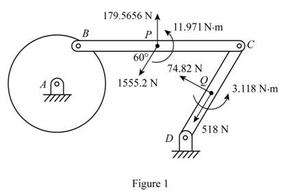
Sketch the effective force and couples on the system as shown in Figure 1.
Sketch the Free Body Diagram of the rod BC as shown in Figure 2.
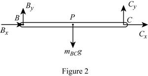
Refer to Figure 2.
Apply the Equilibrium of moment about B as shown below.
Substitute
Sketch the Free Body Diagram of the rod CD as shown in Figure 3.
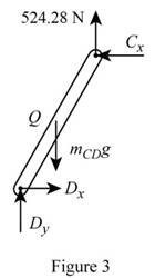
Refer to Figure 3.
Apply the Equilibrium of moment about D as shown below.
Substitute
Sketch the Free Body Diagram of the rod AB and BC as shown in Figure 4.
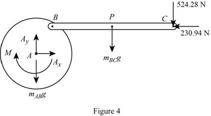
Refer to Figure 4.
Apply the Equilibrium of moment about A as shown below.
Substitute
Therefore, the couple M is
(b)
The components of force exerted at C on rod BC.
Answer to Problem 16.135P
The components of force exerted at C on rod BC is
Explanation of Solution
Given information:
The mass of the rod BC is
The mass of the disk is
The mass of the rod CD is
The angular velocity is
The angular acceleration is
Calculation:
Refer to part (a).
The components of force exerted at C on rod BC along x direction is
The components of force exerted at C on rod BC along y direction is
Therefore, the components of force exerted at C on rod BC is
Want to see more full solutions like this?
Chapter 16 Solutions
VECTOR MECHANIC
Additional Engineering Textbook Solutions
Fluid Mechanics: Fundamentals and Applications
Electric Circuits. (11th Edition)
Experiencing MIS
Starting Out With Visual Basic (8th Edition)
Elementary Surveying: An Introduction To Geomatics (15th Edition)
Thermodynamics: An Engineering Approach


- An Inclining experiment done on a ship thats 6500 t, a mass of 30t was moved 6.0 m transvesly causing a 30 cm deflection in a 6m pendulum, calculate the transverse meta centre height.arrow_forwarda ship 150 m long and 20.5 m beam floats at a draught of8 m and displaces 19 500 tonne. The TPC is 26.5 and midshipsection area coefficient 0.94. Calculate the block, prismatic andwaterplane area coefficients.arrow_forwardA vessel loads 680 t fuel between forward and aft deep tanks. centre of gravity of forward tank is 24m forward of ships COG. centre to centre between tanks is 42 m. how much in each tank to keep trim the samearrow_forward
- Beam of a vessel is 11% its length. Cw =0.72. When floating in SW of relative denisity 1.03, TPC is 0.35t greater than in freshwater. Find the length of the shiparrow_forwardAn inclining experiment was carried out on a ship of 4000tonne displacement, when masses of 6 tonne were moved transverselythrough 13.5 m. The deflections of a 7.5 m pendulurnwere 81, 78, 85, 83, 79, 82, 84 and 80 mm respectively.Caiculate the metacentric height.arrow_forwardA ship of 10 000 tonne displacement has a waterplanearea of 1300 m2. The ship loads in water of 1.010 t/m3 andmoves into water of 1.026 t/m3. Find the change in meandraughtarrow_forward
- A ship of 7000 tonne displacement has a waterplane areaof 1500 m2. In passing from sea water into river water of1005 kg/m3 there is an increase in draught of 10 cm. Find the Idensity of the sea water.arrow_forwardA ship has 300 tonne of cargo in the hold, 24 m forward ofmidships. The displacement of the vessel is 6000 tonne and its centre of gravity is 1.2 m forward of midships.Find the new position of the centre of gravity if this cargo ismoved to an after hold, 40 m from midshipsarrow_forwardSketch and describe how ships are supported in dry dock. When and where does the greatest amount of stresses occur?arrow_forward
- Sketch and desribe a balanced rudder and how it is suspendedarrow_forwardA ship 140 m long and 18 m beam floats at a draught of9 m. The immersed cross-sectionai areas at equai intervais are 5,60, 116, 145, 152, 153, 153, 151, 142, 85 and 0 m2 respectively.Calculate:(a) displacement(b) block coefficient(c) midship section area coefficient(d) prismatic coefficient.arrow_forwardA steamer has waterplane area 1680m2 recorded in water with relative denisty 1.013. Displacement = 1200 t, calculate difference in draught in salwater reltive denisity 1.025.arrow_forward
 Elements Of ElectromagneticsMechanical EngineeringISBN:9780190698614Author:Sadiku, Matthew N. O.Publisher:Oxford University Press
 Mechanics of Materials (10th Edition)Mechanical EngineeringISBN:9780134319650Author:Russell C. HibbelerPublisher:PEARSON
 Thermodynamics: An Engineering ApproachMechanical EngineeringISBN:9781259822674Author:Yunus A. Cengel Dr., Michael A. BolesPublisher:McGraw-Hill Education
 Control Systems EngineeringMechanical EngineeringISBN:9781118170519Author:Norman S. NisePublisher:WILEY
 Mechanics of Materials (MindTap Course List)Mechanical EngineeringISBN:9781337093347Author:Barry J. Goodno, James M. GerePublisher:Cengage Learning
 Engineering Mechanics: StaticsMechanical EngineeringISBN:9781118807330Author:James L. Meriam, L. G. Kraige, J. N. BoltonPublisher:WILEY