
Concept explainers
Videos
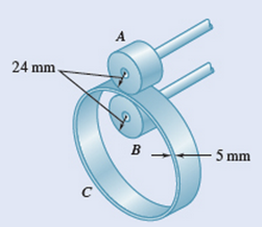
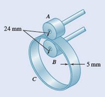
Ring C has an inside radius of 55 mm and an outside radius of 60 mm and is positioned between two wheels A and B, each of 24-mm outside radius. Knowing that wheel A rotates with a constant angular velocity of 300 rpm and that no slipping occurs, determine (a) the angular velocity of ring C and of wheel B, (b) the acceleration of the points on A and B that are in contact with C.
Fig. . P15.26
(a)
The angular velocity of ring
Answer to Problem 15.26P
The angular velocity of ring
The angular velocity of wheel
Explanation of Solution
Given information:
Inside radius of ring
Outside radius of ring
Outside radius of wheels
Wheel
No slipping occurs.
Concept used:
The velocity
Calculation:
The velocity of the point
The point of ring
Here, the outer radius of the ring
The ponit of wheel
Here, the inner radius of the ring
The angular velocity of ring
The angular velocity of wheel
Conclusion:
The angular velocity of ring
The angular velocity of wheel
(b)
The accelerations of the points on
Answer to Problem 15.26P
The accelerations of the point on
The accelerations of the point on
Explanation of Solution
Given information:
Inside radius of ring
Outside radius of ring
Outside radius of wheels
Wheel
No slipping occurs.

Concept used:
The acceleration
Calculation:
The acceleration of the point
Consider the point on
Consider the point on
The accelerations of the point on
The accelerations of the point on
Conclusion:
The accelerations of the point on
The accelerations of the point on
Want to see more full solutions like this?
Chapter 15 Solutions
Vector Mechanics For Engineers


- Qu 5 Determine the carburizing time necessary to achieve a carbon concentration of 0.30 wt% at a position 4 mm into an iron carbon alloy that initially contains 0.10 wt% C. The surface concentration is to be maintained at 0.90 wt% C, and the treatment is to be conducted at 1100°C. Use the data for the diffusion of carbon into y-iron: Do = 2.3 x10⁻⁵ m2/s and Qd = 148,000 J/mol. Express your answer in hours to three significant figures. show all work step by step problems formula material sciencearrow_forward(Read Question)arrow_forwardIn figure A, the homogeneous rod of constant cross section is attached to unyielding supports. In figure B, a homogeneous bar with a cross-sectional area of 600 mm2 is attached to rigid supports. The bar carries the axial loads P1 = 20 kN and P2 = 60 kN, as shown.1. In figure A, derive the expression that calculates the reaction R1 in terms of P, and the given dimensions.2. In figure B, calculate the reaction (kN) at A.3. In figure B, calculate the maximum axial stress (MPa) in the rod.arrow_forward
- (Read image)arrow_forward(Read Image)arrow_forwardM16x2 grade 8.8 bolts No. 25 C1- Q.2. The figure is a cross section of a grade 25 cast-iron pressure vessel. A total of N, M16x2.0 grade 8.8 bolts are to be used to resist a separating force of 160 kN. (a) Determine ks, km, and C. (b) Find the number of bolts required for a load factor of 2 where the bolts may be reused when the joint 19 mm is taken apart. (c) with the number of bolts obtained in (b), determine the realized load factor for overload, the yielding factor of safety, and the separation factor of safety. 19 mmarrow_forward
- Problem4. The thin uniform disk of mass m = 1-kg and radius R = 0.1m spins about the bent shaft OG with the angular speed w2 = 20 rad/s. At the same time, the shaft rotates about the z-axis with the angular speed 001 = 10 rad/s. The angle between the bent portion of the shaft and the z-axis is ẞ = 35°. The mass of the shaft is negligible compared to the mass of the disk. a. Find the angular momentum of the disk with respect to point G, based on the axis orientation as shown. Include an MVD in your solution. b. Find the angular momentum of the disk with respect to point O, based on the axis orientation as shown. (Note: O is NOT the center of fixed-point rotation.) c. Find the kinetic energy of the assembly. z R R 002 2R x Answer: H = -0.046ĵ-0.040 kg-m²/sec Ho=-0.146-0.015 kg-m²/sec T 0.518 N-m =arrow_forwardProblem 3. The assembly shown consists of a solid sphere of mass m and the uniform slender rod of the same mass, both of which are welded to the shaft. The assembly is rotating with angular velocity w at a particular moment. Find the angular momentum with respect to point O, in terms of the axes shown. Answer: Ñ。 = ½mc²wcosßsinßĵ + (}{mr²w + 2mb²w + ½ mc²wcos²ß) k 3 m r b 2 C لا marrow_forwardOnly question 2arrow_forward
- Only question 1arrow_forwardOnly question 3arrow_forwardI have Euler parameters that describe the orientation of N relative to Q, e = -0.7071*n3, e4 = 0.7071. I have Euler parameters that describe the orientation of U relative to N, e = -1/sqrt(3)*n1, e4 = sqrt(2/3). After using euler parameter rule of successive rotations, I get euler parameters that describe the orientation of U relative to Q, e = -0.4082*n1 - 0.4082*n2 - 0.5774*n3. I need euler parameters that describe the orientation of U relative to Q in vector basis of q instead of n. How do I get that?arrow_forward
 Elements Of ElectromagneticsMechanical EngineeringISBN:9780190698614Author:Sadiku, Matthew N. O.Publisher:Oxford University Press
 Mechanics of Materials (10th Edition)Mechanical EngineeringISBN:9780134319650Author:Russell C. HibbelerPublisher:PEARSON
 Thermodynamics: An Engineering ApproachMechanical EngineeringISBN:9781259822674Author:Yunus A. Cengel Dr., Michael A. BolesPublisher:McGraw-Hill Education
 Control Systems EngineeringMechanical EngineeringISBN:9781118170519Author:Norman S. NisePublisher:WILEY
 Mechanics of Materials (MindTap Course List)Mechanical EngineeringISBN:9781337093347Author:Barry J. Goodno, James M. GerePublisher:Cengage Learning
 Engineering Mechanics: StaticsMechanical EngineeringISBN:9781118807330Author:James L. Meriam, L. G. Kraige, J. N. BoltonPublisher:WILEY