
Concept explainers
Videos
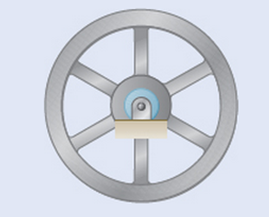
The motion of an oscillation flywheel is defined by the relation
(a)
The angular coordinate, the angular velocity and the angular acceleration of the flywheel when
Answer to Problem 15.3P
The angular coordinate of the flywheel
The angular velocity of the flywheel
The angular acceleration of the flywheel
Explanation of Solution
Given information:
The motion of the flywheel is defined by,
Concept used:
The angular velocity,
The angular acceleration,
Calculation:
The motion of the flywheel is defined by,
Thus, at
The angular velocity,
Thus, at
The angular acceleration,
Thus, at
The angular coordinate of the flywheel
The angular velocity of the flywheel
The angular acceleration of the flywheel
Conclusion:
The angular coordinate of the flywheel
The angular velocity of the flywheel
The angular acceleration of the flywheel
(b)
Determine the angular coordinate, the angular velocity and the angular acceleration of the flywheel when
Answer to Problem 15.3P
The angular coordinate of the flywheel,
The angular velocity of the flywheel
The angular acceleration of the flywheel
Explanation of Solution
Given information:
The motion of the flywheel is defined by,
Concept used:
The angular velocity,
The angular velocity,
The angular acceleration,
Calculation:
The motion of the flywheel is defined by,
Thus, at
The angular velocity,
Thus, at
The angular acceleration,
Thus, at
The angular coordinate of the flywheel,
The angular velocity of the flywheel
The angular acceleration of the flywheel
Conclusion:
The angular coordinate of the flywheel,
The angular velocity of the flywheel
The angular acceleration of the flywheel
Want to see more full solutions like this?
Chapter 15 Solutions
Vector Mechanics For Engineers


- CORRECT AND DETAILED HANDWRITTEN SOLUTION WITH FBD ONLY. I WILL UPVOTE THANK YOU. CORRECT ANSWER IS ALREADY PROVIDED. A concrete wall retains water as shown. Assume that the wall is fixed at the base. Given: H = 3 m, t = 0.5m, Concrete unit weight = 23 kN/m3Unit weight of water = 9.81 kN/m3(Hint: The pressure of water is linearly increasing from the surface to the bottom with intensity 9.81d.)1. Find the maximum compressive stress (MPa) at the base of the wall if the water reaches the top.2. If the maximum compressive stress at the base of the wall is not to exceed 0.40 MPa, what is the maximum allowable depth(m) of the water?3. If the tensile stress at the base is zero, what is the maximum allowable depth (m) of the water?ANSWERS: (1) 1.13 MPa, (2) 2.0 m, (3) 1.20 marrow_forwardCORRECT AND DETAILED HANDWRITTEN SOLUTION WITH FBD ONLY. I WILL UPVOTE THANK YOU. CORRECT ANSWER IS ALREADY PROVIDED. A short plate is attached to the center of the shaft as shown. The bottom of the shaft is fixed to the ground.Given: a = 75 mm, h = 125 mm, D = 38 mmP1 = 24 kN, P2 = 28 kN1. Calculate the maximum torsional stress in the shaft, in MPa.2. Calculate the maximum flexural stress in the shaft, in MPa.3. Calculate the maximum horizontal shear stress in the shaft, in MPa.ANSWERS: (1) 167.07 MPa; (2) 679.77 MPa; (3) 28.22 MPaarrow_forwardA counter flow double pipe heat exchanger is being used to cool hot oil from 320°F to 285°F using cold water. The water, which flows through the inner tube, enters the heat exchanger at 70°F and leaves at 175°F. The inner tube is ¾-std type L copper. The overall heat transfer coefficient based on the outside diameter of the inner tube is 140 Btu/hr-ft2-°F. Design conditions call for a total heat transfer duty (heat transfer rate between the two fluids) of 20,000 Btu/hr. Determine the required length of this heat exchanger (ft).arrow_forward
- ! Required information A one-shell-pass and eight-tube-passes heat exchanger is used to heat glycerin (cp=0.60 Btu/lbm.°F) from 80°F to 140°F by hot water (Cp = 1.0 Btu/lbm-°F) that enters the thin-walled 0.5-in-diameter tubes at 175°F and leaves at 120°F. The total length of the tubes in the heat exchanger is 400 ft. The convection heat transfer coefficient is 4 Btu/h-ft²°F on the glycerin (shell) side and 70 Btu/h-ft²°F on the water (tube) side. NOTE: This is a multi-part question. Once an answer is submitted, you will be unable to return to this part. Determine the rate of heat transfer in the heat exchanger before any fouling occurs. Correction factor F 1.0 10 0.9 0.8 R=4.0 3.0 2.0.15 1.0 0.8.0.6 0.4 0.2 0.7 0.6 R= T1-T2 12-11 0.5 12-11 0 0.1 0.2 0.3 0.4 0.5 0.6 0.7 0.8 0.9 1.0 (a) One-shell pass and 2, 4, 6, etc. (any multiple of 2), tube passes P= T₁-11 The rate of heat transfer in the heat exchanger is Btu/h.arrow_forward! Required information Air at 25°C (cp=1006 J/kg.K) is to be heated to 58°C by hot oil at 80°C (cp = 2150 J/kg.K) in a cross-flow heat exchanger with air mixed and oil unmixed. The product of heat transfer surface area and the overall heat transfer coefficient is 750 W/K and the mass flow rate of air is twice that of oil. NOTE: This is a multi-part question. Once an answer is submitted, you will be unable to return to this part. Air Oil 80°C Determine the effectiveness of the heat exchanger.arrow_forwardIn an industrial facility, a counter-flow double-pipe heat exchanger uses superheated steam at a temperature of 155°C to heat feed water at 30°C. The superheated steam experiences a temperature drop of 70°C as it exits the heat exchanger. The water to be heated flows through the heat exchanger tube of negligible thickness at a constant rate of 3.47 kg/s. The convective heat transfer coefficient on the superheated steam and water side is 850 W/m²K and 1250 W/m²K, respectively. To account for the fouling due to chemical impurities that might be present in the feed water, assume a fouling factor of 0.00015 m²-K/W for the water side. The specific heat of water is determined at an average temperature of (30 +70)°C/2 = 50°C and is taken to be J/kg.K. Cp= 4181 Water Steam What would be the required heat exchanger area in case of parallel-flow arrangement? The required heat exchanger area in case of parallel-flow arrangement is 1m².arrow_forward
- A single-pass crossflow heat exchanger is used to cool jacket water (cp = 1.0 Btu/lbm.°F) of a diesel engine from 190°F to 140°F, using air (Cp = 0.245 Btu/lbm.°F) at inlet temperature of 90°F. Both air flow and water flow are unmixed. If the water and air mass flow rates are 85500 lbm/h and 400,000 lbm/h, respectively, determine the log mean temperature difference for this heat exchanger. Assume the correction factor F to be 0.92. Air flow (unmixed) Water flow (unmixed) The log mean temperature difference of the heat exchanger is °F.arrow_forwardusing the theorem of three moments, find all the reactions and supports, I need concise calculations only. the answers are at the bottom, I need concise steps and minimal explanationsarrow_forwardIn an industrial facility, a counter-flow double-pipe heat exchanger uses superheated steam at a temperature of 155°C to heat feed water at 30°C. The superheated steam experiences a temperature drop of 70°C as it exits the heat exchanger. The water to be heated flows through the heat exchanger tube of negligible thickness at a constant rate of 3.47 kg/s. The convective heat transfer coefficient on the superheated steam and water side is 850 W/m²K and 1250 W/m²K, respectively. To account for the fouling due to chemical impurities that might be present in the feed water, assume a fouling factor of 0.00015 m² K/W for the water side. The specific heat of water is determined at an average temperature of (30+70)°C/2 = 50°C and is taken to be Cp J/kg-K. Water Steam Determine the heat exchanger area required to maintain the exit temperature of the water to a minimum of 70°C. The heat exchanger area required isarrow_forward
- Stress, ksi 160 72 150- 140 80 70 ༄ ྃ ༈ ཎྜ རྦ ༅ ཎྜ ྣཧྨ ➢ 130 120 110 100 90 2.0 2.8 3.6 4.4 5 Wire diameter, mm 6.0 6.8 2 7.6 8.4 Compression and extension springs. ASTM A227 Class II Light service Average service 0.020 0.060 0.100 0.140 0.180 0.220 0.260 0.300 0.340 0.380 0.420 0.460 0.500 Wire diameter, in Torsional stress due to initial tension, ksi 10 ४ 20 Preferred range 100 Stress, MPa 9.2 10.0 10.8 11.6 12.4 1100 1035 965 895 825 760 Severe service 690 620 550 50 150 3456789 10 11 12 13 14 15 16 Spring index, C = DJD FIGURE 18-21 Recommended torsional shear stress in an extension spring due to initial tension (Data from Associated Spring, Barnes Group, Inc.) 50 200 485 Stress, MPaarrow_forwardBolted Joint Design Bolted Frames Total Force due to door weight: P = 240 lb Number of Bolts: N = Distance to Bolt C/L: a = 4 N/A Bolt Material - Allowable shear stress of bolt material: T₂ = x Distance from Bolt centroid to bolt: x = y Distance from Bolt centroid to bolt: y = Degrees per Radian- Results y-Load on each bolt: F, = Moment resisted by bolt pattern: M = Radial distance from Bolt centroid to bolt: r = Sum squares of all radial distances: Σr² Force on each bolt to resist moment: F, - Angle for force composition: e= X-Force on each bolt to resist moment: F- y-Force on each bolt to resist moment: Fly Total y-Force on each bolt: Fy = Resultant force on bolt 1: R₁ = Required shear stress area for a bolt: A₂ = ASTM Grade A307 Steel 10,000 0 psi from Table 20-1 3.0 57.296 in degrees lb per bolt lb-in Formula FS-P/N M-Px XB r = (x² + y²)0.5 in² Σ 4r² Mr F₁ = Στ lb degrees lb lb lb Minimum Bolt Diameter: Din = Rounded up Bolt Diameter: D = 55 P. 1.5 in 2 in (3x) 1 in This bracket…arrow_forwardUniversity of Babylon Collage of Engineering/ Al-Musayab Department of Automobiles Final Examination/ Stage: 3rd Notes: Answer 4 questions only 2023-2202 Subject: Theory of vehicles Date: 2023\06\10-Saturday Time: Three Hours Course 2nd Attempt 1st Q1: A Hooke's coupling connects two shafts whose axes are inclined at 30°. The of the driven shaft? Find the maximum value of retardation or acceleration and driving shaft rotates uniformly at 600 rpm. What are the extreme angular velocities state the angle where both will occur. (12.5 Marks) Q2: Four masses, A, B, C, and D), revolve at equal radii and are equally spaced along a shaft. The mass B is 7 kg, and the radius of C and D make angles of 90° and 240°, respectively, with the radius of B. Find the magnitude of the masses A, C, and D and the angular position of A so that the system may be completely balanced. (12.5 Marks) Q3: A cam has straight worked faces that are tangential to a base circle of diameter 90 mm. The follower is a roller…arrow_forward
 Elements Of ElectromagneticsMechanical EngineeringISBN:9780190698614Author:Sadiku, Matthew N. O.Publisher:Oxford University Press
 Mechanics of Materials (10th Edition)Mechanical EngineeringISBN:9780134319650Author:Russell C. HibbelerPublisher:PEARSON
 Thermodynamics: An Engineering ApproachMechanical EngineeringISBN:9781259822674Author:Yunus A. Cengel Dr., Michael A. BolesPublisher:McGraw-Hill Education
 Control Systems EngineeringMechanical EngineeringISBN:9781118170519Author:Norman S. NisePublisher:WILEY
 Mechanics of Materials (MindTap Course List)Mechanical EngineeringISBN:9781337093347Author:Barry J. Goodno, James M. GerePublisher:Cengage Learning
 Engineering Mechanics: StaticsMechanical EngineeringISBN:9781118807330Author:James L. Meriam, L. G. Kraige, J. N. BoltonPublisher:WILEY