(a)
Using the vertical curvature determine minimum length of vertical curve.
Answer to Problem 4P
Explanation of Solution
Given information:
Station
Elevation
Grades
Grades
Design speed of
Calculation:
Length of curve is given by formula,
A is the grade difference between
Rate of vertical curvature from textbook Table
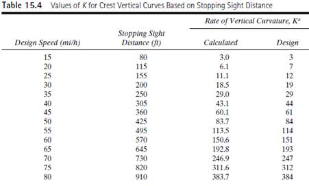
Substitute in equation
Minimum length of vertical curve is
(b)
Stations and elevations of BVC and EVC.
Answer to Problem 4P
Station at BVC is
Tangent elevation at BVC is
Explanation of Solution
Given information:
Station
Elevation
Grades
Grades
Design speed of
Calculation:
Therefore station at BVC is
Therefore tangent elevation at BVC is
(c)
Elevation at each
Answer to Problem 4P
| Station | BVC distance
| Tangent elevation | offset | Curve elevation(Tangent elevation) |
Explanation of Solution
Given information:
Station
Elevation
Grades
Grades
Design speed of
Calculation:
Determine the offset,
For every
| Station | BVC distance
| Tangent elevation | offset | Curve elevation(Tangent elevation) |
(d)
Station and elevation of high point.
Answer to Problem 4P
Explanation of Solution
Given information:
Station
Elevation
Grades
Grades
Design speed of
Calculation:
Distance of the high point of BVC is given by,
Difference beteween both elevation of BVC and highpoint.
Conclusion:
Therefore elevation of high point is
Want to see more full solutions like this?
Chapter 15 Solutions
Traffic And Highway Engineering

- NOTE: Use areal methods only for V,M,N diagrams(Do NOT use the equations) (also draw the N diagram(s) for the entire structure)arrow_forwardNOTE: Use areal methods only for V,M,N diagrams(Do NOT use the equations) (also draw the N diagram(s) for the entire structure)arrow_forwardNOTE: Use areal methods only for V,M,N diagrams(Do NOT use the equations) (also draw the N diagram(s) for the entire structure)arrow_forward
- Problem 2: Use the table below to compute the coordinates of the centroid of area shown below. y – 3 in.—|— 4 in. - -3 3 in. 3 in. x Area X X * Area y Y * Area Component (in²) (in) (in³) (in) (in³) Square 1 Rectangle 2 Triangle 3 Rectangle 4 Σarrow_forwardA shallow foundation measuring 1 m × 2 m in plan is to be constructed over a normally consolidated sand layer. Given: D₁ = 1 m, №60 increases with depth, N 60 (in the depth of stress influence) = 11, Estimate the elastic settlement using Burland and Burbidge's method. (Enter your answer to three significant figures.) Se mm and Inet = 138 kN/m².arrow_forwardA continuous foundation on a deposit of sand layer is shown in the figure below along with the variation of the cone penetration resistance qc 1.5 m 0 2.5 m Sand 14 q= 195 kN/m² qe (kN/m²) 9 1750 93450 9c=2900 Depth (m) Assuming = 16 kN/m² and creep is at the end of ten years after construction, calculate the elastic settlement of the foundation using the strain influence factor method. Use the equations 22 Iz Es 0 | Se = C₁C2 (9) Az and Es = 3.5qc (for L/B> 10) (Enter your answer to three significant figures.) Se = mmarrow_forward
- nent 6-Transverse Shear & Deflection ↓ 2 of 2 -+ Automatic Zoom 4.) The built-up wooden beam shown is subjected to a vertical shear of 8 kN. Knowing the the nails are spaced longitudinally every 60 mm at A and every 25 mm at B, determine the shear force in the nails at A and B. (5 points) 50 300- 400 A 50 A C 150 B A 100 50 200 A B Dimensions in mm 5.) A 2.5 inch x 5.5 inch rectangular Southern pine section (E=1.8 x 10³ ksi) is used in an 8 ft cantilever span subjected to the loads shown. Compute the deflections at point A. (4 points) Дarrow_forwardE:/school%20pack/BENG%202/EG231/STATICS/LECTURE%20NOTES/PRACTICE%20QUESTIONS/EG%20231%20Chap-5%20Practice%20Que PDF 豆豆豆豆豆豆 aw V Aa | Ask Copilot - + 4 of 8 D 3. Calculate the y-coordinate of the centroid of the shaded area. 74 mm y 3232 mm mm DELL 32 mm -x F1 F2 F3 F4 F5 F6 F7 F8 F9 prt sc F10 home end F11 F 2 W E3 $ 4 € 95 % & 6 7 8 * 00 R T Y כ 9 O Parrow_forward*8-60. The 2-in.-diameter rod is subjected to the forces shown. Determine the state of stress at point B, and show the results on a differential element located at this point. Probs. 8-59/60 B 8 in. 600 lb 12 in. 500 lb 800 lbarrow_forward
 Traffic and Highway EngineeringCivil EngineeringISBN:9781305156241Author:Garber, Nicholas J.Publisher:Cengage Learning