
Find the factors of safety with respect to overturning, sliding, and bearing capacity failure.
Answer to Problem 15.2P
The factor of safety with respect to overturning is
The factor of safety with respect to sliding is
The factor of safety with respect to bearing capacity failure is
Explanation of Solution
Given information:
The cohesion
The unit weight
The friction angle
The unit weight
The backfill angle
Calculation:
Check stability with respect to overturning.
Consider point C as the left end of the toe base as named as C.
Divide the retaining wall into section as in Figure 1.
Sketch the section of the retaining wall as shown in Figure 1.
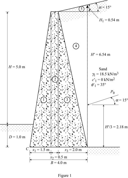
Here,
Refer Table 14.2, “Values of
Take the value of active earth pressure coefficient
Refer Figure 1.
Find the height of the inclined portion of backfill
Substitute 2 m for
Find the total height of the inclined backfill
Here, H is the height of retaining wall and D is the depth to the bottom of the base slab.
Substitute 5.0 m for H, 1.0 m for D, and 0.54 m
Find the active earth pressure
Substitute
Find the vertical component of the active earth pressure
Substitute
Find the horizontal component of the active earth pressure
Substitute
Find the weight of section 1
Here,
Substitute 1.5 m for
Find the moment arm or lever arm
Substitute 1.5 m for
Find the moment about point C
Substitute
Find the weight of section 2
Here,
Substitute 0.5 m for
Find the moment arm or lever arm
Substitute 1.5 m for
Find the moment about point C
Substitute
Find the weight of section 3
Here,
Substitute 2.0 m for
Find the moment arm or lever arm
Substitute 0.5 m for
Find the moment about point C
Substitute
Find the weight of section 4
Here,
Substitute 2.0 m for
Find the moment arm or lever arm
Substitute 2.0 m for
Find the moment about point C
Substitute
Find the weight of section 5
Substitute 2.0 m for
Find the moment arm or lever arm
Substitute 2.0 m for
Find the moment about point C
Substitute
Find the moment arm or lever arm
Substitute 0.5 m for
Find the moment about point C
Substitute
Find the total moment about the point C
Substitute
Find the total vertical load
Substitute
Summarize the values of weight, moment arm from C, and moment about C as shown in Table 1.
| Section | Weight (kN/m) | moment arm from C | moment about C |
| 1 | 108 | 1 | 108 |
| 2 | 72 | 1.75 | 126 |
| 3 | 144 | 2.67 | 384.5 |
| 4 | 111 | 3.33 | 369.6 |
| 5 | 10 | 3.33 | 33.33 |
| 4 | 121.6 | ||
Find the overturning moment
Substitute
Find the factor of safety
Substitute
Therefore, the factor of safety with respect to overturning is
Check the stability with respect to sliding.
Find the coefficient of passive earth pressure
Substitute
Find the passive earth pressure
Here,
Substitute 1 m for D,
Find the angle of friction
Substitute
Find the factor of safety against sliding
Substitute
Therefore, the factor of safety with respect to sliding is
Check the stability with bearing capacity failure.
Find the eccentricity (e) using the equation:
Substitute 4 m for B,
Check for eccentricity.
Substitute 0.116 m for e and 4 m for B.
The eccentricity is within the limit. Therefore, there is no tensile stress produced at the end of the steel section.
Find the maximum pressure
Substitute
Find the effective breadth
Substitute 4 m for B and 0.116 m for e.
Refer Table 16.2, “Bearing Capacity Factors” in the textbook.
Take the value of bearing capacity factor,
Take the value of bearing capacity factor,
Take the value of bearing capacity factor,
Find the load (q) due the soil in front of heel using the equation:
Substitute 1.0 m for D and
Find the inclination angle of vertical load
Substitute
Find the inclination factor
Substitute
Find the depth factor
Here,
Substitute
The depth factor
Find the inclination factor
Substitute
Find the ultimate bearing capacity of the shallow foundation
Substitute
Find the factor of safety against bearing capacity failure
Substitute
Therefore, the factor of safety with respect to bearing capacity failure is
Want to see more full solutions like this?
Chapter 15 Solutions
Fundamentals of Geotechnical Engineering (MindTap Course List)

- I need detailed help solving this exercise from homework of Engineering Mathematics II.I do not really understand how to do, please do it step by step, not that long but clear. Thank you!P.S.: Please do not use AI, thanks!arrow_forwardI need detailed help solving this exercise from homework of Engineering Mathematics II.I do not really understand how to do, please do it step by step, not that long but clear. Thank you!P.S.: Please do not use AI, thanks!arrow_forwardI need detailed help solving this exercise from homework of Engineering Mathematics II.I do not really understand how to do, please do it step by step, not that long but clear. Thank you!P.S.: Please do not use AI, thanks!arrow_forward
- I need detailed help solving this exercise from homework of Engineering Mathematics II.I do not really understand how to do, please do it step by step, not that long but clear. Thank you!P.S.: Please do not use AI, thanks!arrow_forwardI need detailed help solving this exercise from homework of Engineering Mathematics II.I do not really understand how to do, please do it step by step, not that long but clear. Thank you!P.S.: Please do not use AI, thanks!arrow_forwardB1.For the truss below, take P₁ = 4 kip and P₂ = 3 kip: a. Determine all member forces. Hint: first find zero-force members (16 pts). b. Use a section cut to verify your answers for members JI, BI, and BC (4 Pts) В 18 ft 6 ft H B 6 ft C 8 ft D p81 8 ft E 8 ft 6 ft F6ftarrow_forward
- Q13: The line CD, C(xc, 6), D(6,yd), the point D is on the right of point C, the value of horizontal effect H(3,0) is on the right of point C, the vertical effect V(0, -2) right of H. the distance between projection of the points H, V is 5cm, Find: 1- The value of xc and yd. 2- The distance between projections of the points C, D. 3- The true length (T.L.) of CD. 4- The angles a and ẞ. 5- A point F in the middle of line CD, find F (xf, yf).arrow_forwardQ9: The straight line AB of true length (8) cm, having the following data: A (5, ya) & B (xb, yb), the point B is on the left of point A, the inclination of the line to the horizontal plane (H.P) is 30° (a) it Horizontal trace H (-3, 0), and point H is on the left of point A with distance (16) cm. Draw the Plan & Elevation of the line AB and determine the following: 1. The missed coordinates: ya, xb, yb. 2. The coordinates of the vertical trace (V). 3. The inclination of the line to the vertical plane (V.P) (B). 4. The distance between projections of the points A and Barrow_forwardQ12: The straight line AB, having the following data: the distance between projections of the points A and B is 8 cm, and A (2.5, 0) & B (0, 6), the point B is on the left of point A. Draw the Plan & Elevation of the line AB and determine the following: 1. The true length T.L of the line AB. 2. The coordinate of Vertical trace V and Horizontal trace H. 3. The inclination of the line to the V.P and H.P. 4. A point E in the middle of the line AB, find E (xe,ye).arrow_forward
- Deformation of a retaining wall is assumed to be as presented in the figure below. Determine:a) variation of the active and passive pressures on the wall for the presented deformation b) magnitude of the total horizontal force on the right side of the wall.arrow_forward2. a) Consider a cable used for aerial tramway (see figure a). The span is 400 m. The unstretched length of the cable is 402 m. Its mass per unit length is 10kg. The elasticity EA = 10 N. Find the horizontal load on the two ends and the sag d. Determine if the small sag condition is satisfied. b) When a cable car whose mass is 500kg is hung below the cable at a horizontal distance of 100 m from the left end, find the horizontal load on the ends. C) As the car goes along the cable, at which position you will see maximum horizontal load on the two ends?arrow_forwardTwo square surface footings are placed 20 feet apart. Calculate ultimate settlements beneath footing I and at the centerline of the two footings.arrow_forward
 Principles of Foundation Engineering (MindTap Cou...Civil EngineeringISBN:9781337705028Author:Braja M. Das, Nagaratnam SivakuganPublisher:Cengage Learning
 Fundamentals of Geotechnical Engineering (MindTap...Civil EngineeringISBN:9781305635180Author:Braja M. Das, Nagaratnam SivakuganPublisher:Cengage Learning
 Principles of Foundation Engineering (MindTap Cou...Civil EngineeringISBN:9781305081550Author:Braja M. DasPublisher:Cengage Learning
 Principles of Geotechnical Engineering (MindTap C...Civil EngineeringISBN:9781305970939Author:Braja M. Das, Khaled SobhanPublisher:Cengage Learning