
Find the factors of safety with respect to overturning, sliding, and bearing capacity failure.
Answer to Problem 15.2P
The factor of safety with respect to overturning is
The factor of safety with respect to sliding is
The factor of safety with respect to bearing capacity failure is
Explanation of Solution
Given information:
The cohesion
The unit weight
The friction angle
The unit weight
The backfill angle
Calculation:
Check stability with respect to overturning.
Consider point C as the left end of the toe base as named as C.
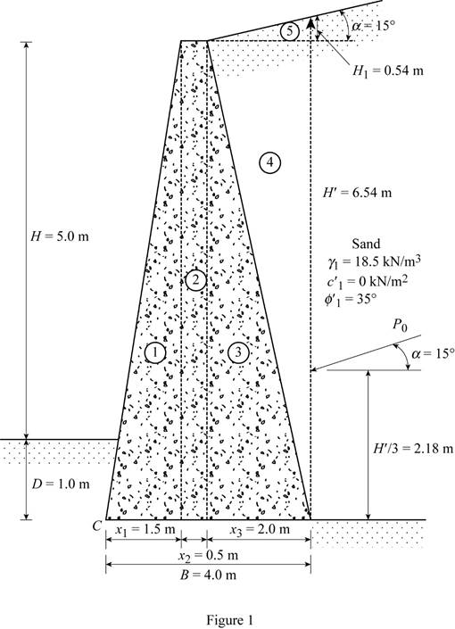
Divide the retaining wall into section as in Figure 1.
Sketch the section of the retaining wall as shown in Figure 1.
Here,
Refer Table 14.2, “Values of
Take the value of active earth pressure coefficient
Refer Figure 1.
Find the height of the inclined portion of backfill
Substitute 2 m for
Find the total height of the inclined backfill
Here, H is the height of retaining wall and D is the depth to the bottom of the base slab.
Substitute 5.0 m for H, 1.0 m for D, and 0.54 m
Find the active earth pressure
Substitute
Find the vertical component of the active earth pressure
Substitute
Find the horizontal component of the active earth pressure
Substitute
Find the weight of section 1
Here,
Substitute 1.5 m for
Find the moment arm or lever arm
Substitute 1.5 m for
Find the moment about point C
Substitute
Find the weight of section 2
Here,
Substitute 0.5 m for
Find the moment arm or lever arm
Substitute 1.5 m for
Find the moment about point C
Substitute
Find the weight of section 3
Here,
Substitute 2.0 m for
Find the moment arm or lever arm
Substitute 0.5 m for
Find the moment about point C
Substitute
Find the weight of section 4
Here,
Substitute 2.0 m for
Find the moment arm or lever arm
Substitute 2.0 m for
Find the moment about point C
Substitute
Find the weight of section 5
Substitute 2.0 m for
Find the moment arm or lever arm
Substitute 2.0 m for
Find the moment about point C
Substitute
Find the moment arm or lever arm
Substitute 0.5 m for
Find the moment about point C
Substitute
Find the total moment about the point C
Substitute
Find the total vertical load
Substitute
Summarize the values of weight, moment arm from C, and moment about C as shown in Table 1.
| Section | Weight (kN/m) | moment arm from C | moment about C |
| 1 | 108 | 1 | 108 |
| 2 | 72 | 1.75 | 126 |
| 3 | 144 | 2.67 | 384.5 |
| 4 | 111 | 3.33 | 369.6 |
| 5 | 10 | 3.33 | 33.33 |
| 4 | 121.6 | ||
Find the overturning moment
Substitute
Find the factor of safety
Substitute
Therefore, the factor of safety with respect to overturning is
Check the stability with respect to sliding.
Find the coefficient of passive earth pressure
Substitute
Find the passive earth pressure
Here,
Substitute 1 m for D,
Find the angle of friction
Substitute
Find the factor of safety against sliding
Substitute
Therefore, the factor of safety with respect to sliding is
Check the stability with bearing capacity failure.
Find the eccentricity (e) using the equation:
Substitute 4 m for B,
Check for eccentricity.
Substitute 0.116 m for e and 4 m for B.
The eccentricity is within the limit. Therefore, there is no tensile stress produced at the end of the steel section.
Find the maximum pressure
Substitute
Find the effective breadth
Substitute 4 m for B and 0.116 m for e.
Refer Table 16.2, “Bearing Capacity Factors” in the textbook.
Take the value of bearing capacity factor,
Take the value of bearing capacity factor,
Take the value of bearing capacity factor,
Find the load (q) due the soil in front of heel using the equation:
Substitute 1.0 m for D and
Find the inclination angle of vertical load
Substitute
Find the inclination factor
Substitute
Find the depth factor
Here,
Substitute
The depth factor
Find the inclination factor
Substitute
Find the ultimate bearing capacity of the shallow foundation
Substitute
Find the factor of safety against bearing capacity failure
Substitute
Therefore, the factor of safety with respect to bearing capacity failure is
Want to see more full solutions like this?
Chapter 15 Solutions
EBK FUNDAMENTALS OF GEOTECHNICAL ENGINE

- Please explain step by step, and show formulaarrow_forwardNote: Please deliver a clear, step-by-step simplified handwritten solution (without any explanations) that is entirely manually produced without AI assistance. I expect an expert-level answer, and I will evaluate and rate it based on the quality and accuracy of the work, using the provided image for additional reference. Ensure every detail is thoroughly checked for correctness before submission.arrow_forwardPlease don't explain it. But draw it out for me kindly. And appreciate your time!. All the info is in the images. Thanks!.arrow_forward
- Design a simply supported one-way pavement slab for a factored applied moment, Mu = 10 ft-kip. Use f c’ = 5,000 psi and f y = 60,000 psi. The slab is in permanent contact with soil.Hint:• Estimate a minimum slab thickness for deflection control.• Solve for the slab steel based on cover for soil contactarrow_forwardThe figures below shows the framing plan and section of a reinforced concrete floor system. Floor beams are shown as dotted lines. The weight of the ceiling and floor finishing is 6 psf, that of the mechanical and electrical systems is 7 psf, and the weight of the partitions is 180 psf. The floor live load is 105 psf. The 7 in. thick slab exterior bay (S-1) is reinforced with #5 rebars @ 10 in. o.c. as the main positive reinforcement at the mid span, and #4 @ 109 in. for the shrinkage and temperature reinforcement. The panel is simply supported on the exterior edge and monolithic with the beam at the interior edge. Check the adequacy of the slab. Use the ACI moment coefficients. fc’ = 6,000 psi and fy = 60,000 psi. The slab is in an interior location. Hint: • Estimate total dead load. Find factored maximum positive bending moment in the end span. • Find design positive moment capacity. • Compare and determine adequacy, including safety and economy.arrow_forward1 For an reinforced concrete two-way slab shown in figure under the load (P). (the slab continuous over all edges - all sides are fixed), Determine (By using yield line theory): A- Draw the Yield line Pattern B- Determine the moment m C- Find The required flexural steel to resist the loads causing the slab to collapse if P = 200 KN, f=28 MPa, fy = 420 MPa d = 120 mm. Use 10 mm bars. (Prin = 0.002) +2 m 6 m -8 m 3 marrow_forward
- At a point on the surface of a generator shaft the stresses are σx = -55MPa, σy = 25MPa and Txy = -20MPa as shown in Figure Q1. (a) Using either analytical method or Mohr's circle determine the following: Stresses acting on an element inclined at an angle 0 = 35°, i. ii. iii. The maximum shear stress The principal stresses and B. 25 MPa A 55 MPa 20 MPa Figure 1:Material stress state (b) Consider that the Young's modulus for the material, E = 200kPa and Poisson's ratio, v = 0.25. i. ii. determine associate strains for the material with the stress as shown in Figure 1 determine associate strains for the material with the stress at element oriented at 35° (question 1a(i))arrow_forwardA study reports data on the effects of the drug tamoxifen on change in the level of cortisol-binding globulin (CBG) of patients during treatment. With age = x and ACBG = y, summary values are n = 26, Σx, = 1612, Σ(x, - x)² = 3756.96, Σy, = 281.9, Σ(y, - y)² = 465.34, and Ex,y,= 16,745. (a) Compute a 90% CI for the true correlation coefficient p. (Round your answers to four decimal places.) (b) Test Hop=-0.5 versus H: p< -0.5 at level 0.05. Calculate the test statistic and determine the P-value. (Round your test statistic to two decimal places and your P-value to four decimal places.) z = P-value = State the conclusion in the problem context. ◇ Reject Ho. There is no evidence that p < -0.5. ○ Fail to reject Ho. There is evidence that p < -0.5. Reject Ho. There is evidence that p < -0.5. Fail to reject Ho. There is no evidence that p < -0.5. (c) In a regression analysis of y on x, what proportion of variation in change of cortisol-binding globulin level could be explained by variation in…arrow_forwardFor the frame and loading shown, determine the reactions at A and C. 24 Last 2 student ID+50 lbs 24 A 3 in. B A=Last 2 student ID+10 Inch B=Last 2 student ID+40 Inch A B Darrow_forward
- The figures below shows the framing plan and section of a reinforced concrete floor system. Floor beams are shown as dotted lines. The weight of the ceiling and floor finishing is 6 psf, that of the mechanical and electrical systems is 7 psf, and the weight of the partitions is 180 psf. The floor live load is 105 psf. The 7 in. thick slab exterior bay (S-1) is reinforced with #5 rebars @ 10 in. o.c. as the main positive reinforcement at the mid span, and #4 @ 109 in. for the shrinkage and temperature reinforcement. The panel is simply supported on the exterior edge and monolithic with the beam at the interior edge. Check the adequacy of the slab. Use the ACI moment coefficients. fc’ = 6,000 psi and fy = 60,000 psi. The slab is in an interior location. Hint: • Estimate total dead load. Find factored maximum positive bending moment in the end span. • Find design positive moment capacity. • Compare and determine adequacy, including safety and economy. C Darrow_forwardFor an reinforced concrete two-way slab shown in figure under the load (P). (the slab continuous over all edges - all sides are fixed), Determine (By using yield line theory): A- Draw the Yield line Pattern B- Determine the moment m C- Find The required flexural steel to resist the loads causing the slab to collapse if P = 200 KN, f=28 MPa, fy = 420 MPa d = 120 mm. Use 10 mm bars. Draw the yield line and (Qmin = 0.002) 2m solve PO 6 m 3 m -8 marrow_forwardFind the internal torques for segments AB, BC, and CD (in N-m) by drawing the internal torque diagram, the maximum torsional shear on the shaft in MPa, and the relative rotation of section A with respect to section D in degrees.arrow_forward
 Principles of Foundation Engineering (MindTap Cou...Civil EngineeringISBN:9781337705028Author:Braja M. Das, Nagaratnam SivakuganPublisher:Cengage Learning
 Fundamentals of Geotechnical Engineering (MindTap...Civil EngineeringISBN:9781305635180Author:Braja M. Das, Nagaratnam SivakuganPublisher:Cengage Learning
 Principles of Foundation Engineering (MindTap Cou...Civil EngineeringISBN:9781305081550Author:Braja M. DasPublisher:Cengage Learning
 Principles of Geotechnical Engineering (MindTap C...Civil EngineeringISBN:9781305970939Author:Braja M. Das, Khaled SobhanPublisher:Cengage Learning