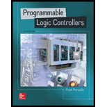
Programmable Logic Controllers
5th Edition
ISBN: 9780073373843
Author: Frank D. Petruzella
Publisher: McGraw-Hill Education
expand_more
expand_more
format_list_bulleted
Concept explainers
Textbook Question
Chapter 14, Problem 5P
- a. Calculate the proportional band of a temperature controller with a 5% bandwidth and a set-point of 500°F.
- b. Calculate the upper and lower limits beyond which the controller functions as an on/off unit.
Expert Solution & Answer
Want to see the full answer?
Check out a sample textbook solution
Students have asked these similar questions
Write a program that simulates a Magic 8 Ball, which is a fortune-telling toy that displays a random response to a yes or no question. In the student sample programs for this book, you will find a text file named 8_ball_responses.txt. The file contains 12 responses, such as “I don’t think so”, “Yes, of course!”, “I’m not sure”, and so forth. The program should read the responses from the file into a list. It should prompt the user to ask a question, then display one of the responses, randomly selected from the list. The program should repeat until the user is ready to quit.
Contents of 8_ball_responses.txt:
Yes, of course! Without a doubt, yes. You can count on it. For sure! Ask me later. I'm not sure. I can't tell you right now. I'll tell you after my nap. No way! I don't think so. Without a doubt, no. The answer is clearly NO.
(You can access the Computer Science Portal at www.pearsonhighered.com/gaddis.)
Start with the initial angles within the integration and just integrate them without mapping them to specific quadrants. Use python and radians
How does encryption prevent a hacker from getting your data
Chapter 14 Solutions
Programmable Logic Controllers
Ch. 14 - Compare continuous and batch processes.Ch. 14 - Prob. 2RQCh. 14 - State the basic function of each of the following...Ch. 14 - State the purpose of each of the following types...Ch. 14 - Prob. 5RQCh. 14 - Prob. 6RQCh. 14 - Prob. 7RQCh. 14 - Prob. 8RQCh. 14 - Prob. 9RQCh. 14 - Prob. 10RQ
Ch. 14 - Prob. 11RQCh. 14 - What term of a PID control is designed to...Ch. 14 - Prob. 13RQCh. 14 - Prob. 14RQCh. 14 - Prob. 15RQCh. 14 - Prob. 16RQCh. 14 - Prob. 17RQCh. 14 - Prob. 18RQCh. 14 - Prob. 19RQCh. 14 - List four types of communication tasks provided by...Ch. 14 - Prob. 21RQCh. 14 - What are the three general levels of functionality...Ch. 14 - Prob. 23RQCh. 14 - Prob. 24RQCh. 14 - Compare device and process bus networks.Ch. 14 - Prob. 26RQCh. 14 - Prob. 27RQCh. 14 - Prob. 28RQCh. 14 - Prob. 29RQCh. 14 - Summarize the collision detection network access...Ch. 14 - Prob. 31RQCh. 14 - Prob. 32RQCh. 14 - Prob. 33RQCh. 14 - Prob. 34RQCh. 14 - Prob. 35RQCh. 14 - Prob. 36RQCh. 14 - Prob. 37RQCh. 14 - Prob. 38RQCh. 14 - Prob. 39RQCh. 14 - Explain how redundant media works.Ch. 14 - Prob. 41RQCh. 14 - Prob. 42RQCh. 14 - Prob. 43RQCh. 14 - Prob. 44RQCh. 14 - Summarize the two main functions of a SCADA...Ch. 14 - Prob. 46RQCh. 14 - Prob. 1PCh. 14 - Prob. 2PCh. 14 - How would an on/off controller respond if the...Ch. 14 - In a home heating system with on/off control, what...Ch. 14 - a. Calculate the proportional band of a...Ch. 14 - Prob. 6PCh. 14 - Prob. 7PCh. 14 - Prob. 8P
Knowledge Booster
Learn more about
Need a deep-dive on the concept behind this application? Look no further. Learn more about this topic, computer-science and related others by exploring similar questions and additional content below.Similar questions
- what type of internet connection should be avoided on mobile devices?arrow_forwardI need help creating the network diagram and then revising it for the modified activity times.arrow_forwardActivity No. Activity Time (weeks) Immediate Predecessors 1 Requirements collection 3 2 Requirements structuring 4 1 3 Process analysis 3 2 4 Data analysis 3 2 5 Logical design 50 3,4 6 Physical design 5 5 7 Implementation 6 6 c. Using the information from part b, prepare a network diagram. Identify the critical path.arrow_forward
- Given the following Extended-BNF grammar of the basic mathematical expressions: Show the derivation steps for the expression: ( 2 + 3 ) * 6 – 20 / ( 3 + 1 ) Draw the parsing tree of this expression. SEE IMAGEarrow_forwardWhentheuserenters!!,themostrecentcommandinthehistoryisexecuted.In the example above, if the user entered the command: Osh> !! The ‘ls -l’ command should be executed and echoed on user’s screen. The command should also be placed in the history buffer as the next command. Whentheuserentersasingle!followedbyanintegerN,theNthcommandin the history is executed. In the example above, if the user entered the command: Osh> ! 3 The ‘ps’ command should be executed and echoed on the user’s screen. The command should also be placed in the history buffer as the next command. Error handling: The program should also manage basic error handling. For example, if there are no commands in the history, entering !! should result in a message “No commands in history.” Also, if there is no command corresponding to the number entered with the single !, the program should output "No such command in history."arrow_forwardActivity No. Activity Time (weeks) Immediate Predecessors 1 Requirements collection 3 2 Requirements structuring 4 1 3 Process analysis 3 2 4 Data analysis 3 2 5 Logical design 50 3,4 6 Physical design 5 5 7 Implementation 6 6 c. Using the information from part b, prepare a network diagram. Identify the critical path.arrow_forward
- 2. UNIX Shell and History Feature [20 points] This question consists of designing a C program to serve as a shell interface that accepts user commands and then executes each command in a separate process. A shell interface gives the user a prompt, after which the next command is entered. The example below illustrates the prompt osh> and the user's next command: cat prog.c. The UNIX/Linux cat command displays the contents of the file prog.c on the terminal using the UNIX/Linux cat command and your program needs to do the same. osh> cat prog.c The above can be achieved by running your shell interface as a parent process. Every time a command is entered, you create a child process by using fork(), which then executes the user's command using one of the system calls in the exec() family (as described in Chapter 3). A C program that provides the general operations of a command-line shell can be seen below. #include #include #define MAX LINE 80 /* The maximum length command */ { int…arrow_forwardQuestion#2: Design and implement a Java program using Abstract Factory and Singleton design patterns. The program displays date and time in one of the following two formats: Format 1: Date: MM/DD/YYYY Time: HH:MM:SS Format 2: Date: DD-MM-YYYY Time: SS,MM,HH The following is how the program works. In the beginning, the program asks the user what display format that she wants. Then the program continuously asks the user to give one of the following commands, and performs the corresponding task. Note that the program gets the current date and time from the system clock (use the appropriate Java date and time operations for this). 'd' display current date 't': display current time 'q': quit the program. • In the program, there should be 2 product hierarchies: "DateObject” and “TimeObject”. Each hierarchy should have format and format2 described above. • Implement the factories as singletons. • Run your code and attach screenshots of the results. • Draw a UML class diagram for the program.arrow_forward#include <linux/module.h> #include <linux/kernel.h> // part 2 #include <linux/sched.h> // part 2 extra #include <linux/hash.h> #include <linux/gcd.h> #include <asm/param.h> #include <linux/jiffies.h> void print_init_PCB(void) { printk(KERN_INFO "init_task pid:%d\n", init_task.pid); printk(KERN_INFO "init_task state:%lu\n", init_task.state); printk(KERN_INFO "init_task flags:%d\n", init_task.flags); printk(KERN_INFO "init_task runtime priority:%d\n", init_task.rt_priority); printk(KERN_INFO "init_task process policy:%d\n", init_task.policy); printk(KERN_INFO "init_task task group id:%d\n", init_task.tgid); } /* This function is called when the module is loaded. */ int simple_init(void) { printk(KERN_INFO "Loading Module\n"); print_init_PCB(); printk(KERN_INFO "Golden Ration Prime = %lu\n", GOLDEN_RATIO_PRIME); printk(KERN_INFO "HZ = %d\n", HZ); printk(KERN_INFO "enter jiffies = %lu\n", jiffies); return 0; } /* This function is called when the…arrow_forward
arrow_back_ios
SEE MORE QUESTIONS
arrow_forward_ios
Recommended textbooks for you
 Systems ArchitectureComputer ScienceISBN:9781305080195Author:Stephen D. BurdPublisher:Cengage Learning
 Principles of Information Systems (MindTap Course...Computer ScienceISBN:9781305971776Author:Ralph Stair, George ReynoldsPublisher:Cengage Learning
 Principles of Information Systems (MindTap Course...Computer ScienceISBN:9781285867168Author:Ralph Stair, George ReynoldsPublisher:Cengage Learning
 A+ Guide to Hardware (Standalone Book) (MindTap C...Computer ScienceISBN:9781305266452Author:Jean AndrewsPublisher:Cengage Learning
 CompTIA Linux+ Guide to Linux Certification (Mind...Computer ScienceISBN:9781305107168Author:Jason EckertPublisher:Cengage Learning
 EBK JAVA PROGRAMMINGComputer ScienceISBN:9781305480537Author:FARRELLPublisher:CENGAGE LEARNING - CONSIGNMENT

Systems Architecture
Computer Science
ISBN:9781305080195
Author:Stephen D. Burd
Publisher:Cengage Learning

Principles of Information Systems (MindTap Course...
Computer Science
ISBN:9781305971776
Author:Ralph Stair, George Reynolds
Publisher:Cengage Learning

Principles of Information Systems (MindTap Course...
Computer Science
ISBN:9781285867168
Author:Ralph Stair, George Reynolds
Publisher:Cengage Learning

A+ Guide to Hardware (Standalone Book) (MindTap C...
Computer Science
ISBN:9781305266452
Author:Jean Andrews
Publisher:Cengage Learning

CompTIA Linux+ Guide to Linux Certification (Mind...
Computer Science
ISBN:9781305107168
Author:Jason Eckert
Publisher:Cengage Learning

EBK JAVA PROGRAMMING
Computer Science
ISBN:9781305480537
Author:FARRELL
Publisher:CENGAGE LEARNING - CONSIGNMENT
Electrical Engineering: Ch 5: Operational Amp (2 of 28) Inverting Amplifier-Basic Operation; Author: Michel van Biezen;https://www.youtube.com/watch?v=x2xxOKOTwM4;License: Standard YouTube License, CC-BY