
Concept explainers
Videos
For the pump and piping system of Prob. 14-35E, plot the required pump head
The plot between the available head and the capacity of the pump.
Answer to Problem 36EP
The plot between the available head and the capacity of the pump is 
Explanation of Solution
Given information:
The shutoff head is
Write the expression for the required head using the energy balance equation.
Here, the initial pressure is
Write the expression for the roughness factor.
Here, the diameter of the pipe is
Write the expression for the minor losses.
Here, the minor loss coefficient at pipe entrance is
Write the expression for the frictional loss head.
Here, the friction factor is
Write the expression for the available head.
Here, the shutoff head is
Write the expression for the capacity.
Substitute
Write the expression for the Reynolds number.
Here, the density of the water is
Write the expression for the friction factor using the Colebrook equation.
Calculation:
Refer to table A-3E Properties of saturated water to obtain the density of water as
Substitute
Substitute
Substitute
Substitute
Since, the required head is equal to the available head that is
Substitute
Substitute
Substitute
Substitute
Substitute
Substitute
The different values of the capacity and the available head is shown in the below Table.
| S.No. | Capacity | Available head |
| 1 | ||
| 2 | ||
| 3 | ||
| 4 |
Draw the plot between the available head and the capacity of the pump for different values along with the required head.
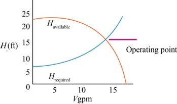
Figure-(1)
Conclusion:
The plot between the available head and the capacity of the pump is 
Want to see more full solutions like this?
Chapter 14 Solutions
FLUID MECHANICS FUND. (LL)-W/ACCESS


- Given that an L-shaped member (OAB) can rotate about OA, determine the moment vector created by the force about the line OA at the instant shown in the figure below. OA lies in the xy-plane, and the AB part is vertical. Express your answer as a Cartesian vector.arrow_forwardDetermine the magnitude of the moment created by the force about the point A.arrow_forward= MMB 241- Tutorial 1.pdf 2/3 80% + + 10. Determine a ats = 1 m v (m/s) 4 s (m) 2 11. Draw the v-t and s-t graphs if v = 0, s=0 when t=0. a (m/s²) 2 t(s) 12. Draw the v-t graph if v = 0 when t=0. Find the equation v = f(t) for each a (m/s²) 2 segment. 2 -2 13. Determine s and a when t = 3 s if s=0 when t = 0. v (m/s) 2 t(s) t(s) 2arrow_forward
- Q.5) A cylinder is supported by spring AD and cables AB and AC as shown. The spring has an at rest length (unstretched length) of 4 meters. If the maximum allowable tension in cables AB and AC is 200 N, determine (a) the largest mass (kg) of cylinder E the system can support, (b) the necessary spring constant (stiffness) to maintain equilibrium, and (b) the tension (magnitude) in each cable when supporting the maximum load found in part (a). B 4 m 3 m A E 1 m 3 m D 5 marrow_forwardDetermine the moment created by the force about the point O. Express your answer as a Cartesian vector.arrow_forward4. An impeller rotating at 1150 rpm has the following data: b, = 1 ¼ in., b2 = ¾ in., d, = 7 in., d2 = 15 in., B1 = 18", B2 = 20°, cross-sectional area A = Db if vane thickness is neglected. Assuming radial inlet flow, determine the theoretical capacity in gpm head in ft horsepower 5. If the impeller in Problem (4) develops an actual head of 82 ft and delivers 850 gpm at the point of maximum efficiency and requires 22 BHP. Determine overall pump efficiency virtual velocities V2 and W2arrow_forward
- (30 pts) Problem 1 A thin uniform rod of mass m and length 2r rests in a smooth hemispherical bowl of radius r. A moment M mgr 4 is applied to the rod. Assume that the bowl is fixed and its rim is in the horizontal plane. HINT: It will help you to find the length l of that portion of the rod that remains outside the bowl. M 2r a) How many degrees of freedom does this system have? b) Write an equation for the virtual work in terms of the angle 0 and the motion of the center of mass (TF) c) Derive an equation for the variation in the position of the center of mass (i.e., Sŕƒ) a. HINT: Use the center of the bowl as the coordinate system origin for the problem. d) In the case of no applied moment (i.e., M 0), derive an equation that can be used to solve for the equilibrium angle of the rod. DO NOT solve the equation e) In the case of an applied moment (i.e., M = mgr = -) derive an equation that can be used to 4 solve for the equilibrium angle of the rod. DO NOT solve the equation. f) Can…arrow_forwardPlease show all work step by steparrow_forwardCopyright 2013 Pearson Education, publishing as Prentice Hall 2. Determine the force that the jaws J of the metal cutters exert on the smooth cable C if 100-N forces are applied to the handles. The jaws are pinned at E and A, and D and B. There is also a pin at F. E 400 mm 15° D B 30 mm² 80 mm/ 20 mm 15° $15° 20 mm 400 mm 15° 100 N 100 N 15°arrow_forward
- Draw for it make a match which directionarrow_forwardQ.1) Block A is connected to block B by a pulley system as shown. The weights of blocks A and B are 100 lbs and 70 lbs, respectively. Assume negligible friction between the rope and all pulleys as well as between block B and the incline and neglect the mass of all pulleys and cables. Determine the angle 0 required to keep the system in equilibrium. (At least two FBDs must be drawn for full credit) B Ꮎ 000arrow_forwardpls solvearrow_forward
 Elements Of ElectromagneticsMechanical EngineeringISBN:9780190698614Author:Sadiku, Matthew N. O.Publisher:Oxford University Press
 Mechanics of Materials (10th Edition)Mechanical EngineeringISBN:9780134319650Author:Russell C. HibbelerPublisher:PEARSON
 Thermodynamics: An Engineering ApproachMechanical EngineeringISBN:9781259822674Author:Yunus A. Cengel Dr., Michael A. BolesPublisher:McGraw-Hill Education
 Control Systems EngineeringMechanical EngineeringISBN:9781118170519Author:Norman S. NisePublisher:WILEY
 Mechanics of Materials (MindTap Course List)Mechanical EngineeringISBN:9781337093347Author:Barry J. Goodno, James M. GerePublisher:Cengage Learning
 Engineering Mechanics: StaticsMechanical EngineeringISBN:9781118807330Author:James L. Meriam, L. G. Kraige, J. N. BoltonPublisher:WILEY