Repeat Prob. 14-60. but at a water temperature of 80°C. Repeat for 90°C. Discuss.
The maximum volume flow rate at which cavitation occur.
Answer to Problem 61P
The maximum volume flow rate at which cavitation occur is
Explanation of Solution
Given information:
The temperature of the water is
Write the expression for the required head using the energy balance equation.
Here, the initial pressure is
Write expression for the available net positive suction head at the pump inlet.
Here, the saturation pressure is
Write the expression for the minor losses.
Here, the minor loss coefficient due to sharp edge is
Write the expression for the velocity of the water.
Write the expression for the Reynolds number.
Here, the density of the water is
Write the expression for the minor losses.
Write the expression for the required net positive suction head.
Write the expression for the friction factor.
Here, the friction factor is
Calculation:
Refer to the Table-A-7E, "Properties of saturated liquid" to obtain the density of the water as
Substitute
Substitute
Use hit and trial method to obtain the volume flow rate.
Iteration 1 consider the volume flow rate as
Substitute
Substitute
Substitute
Substitute
Substitute
Since, the available net positive suction head is greater than the required net positive suction head hence, cavitation does not occur at this flow rate.
The different iteration are shown in the below Table.
| S.No | |||
| 1 | |||
| 2 | |||
| 3 | |||
| 4 | |||
| 5 | |||
| 6 | |||
| 7 | |||
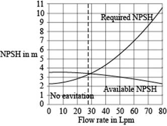
Draw the plot between the flow rate and available net positive suction head and the required net positive suction head.

Figure-(1)
Figure-(1) shows that the cavitation occur at volume flow rates above the
Refer to the Table-A-7E, "Properties of saturated liquid" to obtain the density of the water as
Substitute
Substitute
Use hit and trial method to obtain the volume flow rate.
Iteration 1 consider the volume flow rate as
Substitute
Substitute
Substitute
Substitute
Substitute
Since, the available net positive suction head is greater than the required net positive suction head hence, cavitation does not occur at this flow rate.
The different iteration are shown in the below Table.
| S.No | |||
| 1 | |||
| 2 | |||
| 3 | |||
| 4 | |||
| 5 | |||
| 6 |
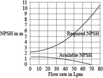
Draw the plot between the flow rate and available net positive suction head and the required net positive suction head.

Figure-(2)
From Figure-(2), available net positive suction head and the required net positive suction head curves are not crossing each other as the temperature of water is near to boiling temperature. The pump cavitates at any flow rate.
Conclusion:
The maximum volume flow rate at which cavitation occurs is
Want to see more full solutions like this?
Chapter 14 Solutions
FLUID MECHANICS FUND. (LL)-W/ACCESS
- 2 レ Tanism in which the link OA mm. O anticlockwise direction at 10 rad/s, the lengths of the various links are OA=75mm, OB=150mm, BC=150mm,CD=300mm. Determine for the position shown, the sliding velocity of D. A A Space Diagram o NT$ (Not-to-Scale) B # C か 750 x2.01 165 79622arrow_forwardAshaft fitted with a flywheel rotates at 300 rpm. and drives a machine. The torque required to drive the machine varies in a cyclic manner over a period of 2 revolutions. The torque drops from 20,000 Nm to 10,000 Nm uniformly during 90 degrees and remains constant for the following 180 degrees. It then rises uniformly to 35,000 Nm during the next 225 degrees and after that it drops to 20,000 in a uniform manner for 225 degrees, the cycle being repeated thereafter. Determine the power required to drive the machine and percentage fluctuation in speed, if the driving torque applied to the shaft is constant and the mass of the flywheel is 12 tonnes with radius of gyration of 500 mm. What is the maximum angular acceleration of the flywheel. 35,000 TNM 20,000 10,000 0 90 270 495 Crank angle 8 degrees 720arrow_forwardFigure below shows a link mechanism in which the link OA rotates uniformly in an anticlockwise direction at 10 rad/s. the lengths of the various links are OA=75 mm, OB-150 mm, BC=150 mm, CD-300 mm. Determine for the position shown, the sliding velocity of D. A 45 B Space Diagram o NTS (Not-to-Scale) C Darrow_forward
- motion is as follows; 1- Dwell 45°. Plot the displacement diagram for a cam with flat follower of width 14 mm. The required 2- Rising 60 mm in 90° with Simple Harmonic Motion. 3- Dwell 90°. 4- Falling 60 mm for 90° with Simple Harmonic Motion. 5- Dwell 45°. Then design the cam profile to give the above displacement diagram if the minimum circle diameter of the cam is 50 mm.arrow_forwardAn ideal gas, occupying a volume of 0.02 m3 , has a temperature of 25 0C and is at 1.2 bar. The gas is compressed reversibly and adiabatically to a final pressure of 8 bar. Assuming the gas has an adiabatic index of γ = 1.4, calculate (a) the final temperature, (b) the final volume, (c) the work performed during the compression and (d) the heat transferred.arrow_forwardattached is a past paper question in which we werent given the solution. a solution with clear steps and justification would be massively appreciated thankyou.arrow_forward
- in this scenario, when it comes to matrix iterations it states this system is assumed out of phase. why is this?arrow_forwardQ1. A curved beam of a circular cross section of diameter "d" is fixed at one end and subjected to a concentrated load P at the free end (Fig. 1). Calculate stresses at points A and C. Given: P = 800 N, d = 30 mm, a 25 mm, and b = 15 mm. Fig.1 P b B (10 Marks)arrow_forwardYou are working as an engineer in a bearing systems design company. The flow of lubricant inside a hydrodynamic bearing (p = 0.001 kg m-1 s-1) can be approximated as a parallel, steady, two-dimensional, incompressible flow between two parallel plates. The top plate, representing the moving part of the bearing, travels at a constant speed, U, while the bottom plate remains stationary (Figure Q1). The plates are separated by a distance of 2h = 1 cm and are W = 20 cm wide. Their length is L = 10 cm. By applying the above approximations to the Navier-Stokes equations and assuming that end effects can be neglected, the horizontal velocity profile can be shown to be y = +h I 2h = 1 cm x1 y = -h u(y) 1 dP 2μ dx -y² + Ay + B moving plate stationary plate U 2 I2 L = 10 cm Figure Q1: Flow in a hydrodynamic bearing. The plates extend a width, W = 20 cm, into the page.arrow_forward
- Question 1 You are working as an engineer in a bearing systems design company. The flow of lubricant inside a hydrodynamic bearing (µ = 0.001 kg m¯¹ s¯¹) can be approximated as a parallel, steady, two-dimensional, incompressible flow between two parallel plates. The top plate, representing the moving part of the bearing, travels at a constant speed, U, while the bottom plate remains stationary (Figure Q1). The plates are separated by a distance of 2h = 1 cm and are W = 20 cm wide. Their length is L = 10 cm. By applying the above approximations to the Navier-Stokes equations and assuming that end effects can be neglected, the horizontal velocity profile can be shown to be 1 dP u(y) = 2μ dx -y² + Ay + B y= +h Ꮖ 2h=1 cm 1 x1 y = −h moving plate stationary plate 2 X2 L = 10 cm Figure Q1: Flow in a hydrodynamic bearing. The plates extend a width, W = 20 cm, into the page. (a) By considering the appropriate boundary conditions, show that the constants take the following forms: U U 1 dP A =…arrow_forwardQuestion 2 You are an engineer working in the propulsion team for a supersonic civil transport aircraft driven by a turbojet engine, where you have oversight of the design for the engine intake and the exhaust nozzle, indicated in Figure Q2a. The turbojet engine can operate when provided with air flow in the Mach number range, 0.60 to 0.80. You are asked to analyse a condition where the aircraft is flying at 472 m/s at an altitude of 14,000 m. For all parts of the question, you can assume that the flow path of air through the engine has a circular cross section. (a) ← intake normal shock 472 m/s A B (b) 50 m/s H 472 m/s B engine altitude: 14,000 m exhaust nozzle E F exit to atmosphere diameter: DE = 0.30 m E F diameter: DF = 0.66 m Figure Q2: Propulsion system for a supersonic aircraft. a) When the aircraft is at an altitude of 14,000 m, use the International Standard Atmosphere in the Module Data Book to state the local air pressure and tempera- ture. Thus show that the aircraft speed…arrow_forwardيكا - put 96** I need a detailed drawing with explanation or in wake, and the top edge of im below the free surface of the water. Determine the hydrothed if hydrostatic on the Plot the displacement diagram for a cam with roller follower of diameter 10 mm. The required motion is as follows; 1- Rising 60 mm in 135° with uniform acceleration and retardation motion. 2- Dwell 90° 3- Falling 60 mm for 135° with Uniform acceleration-retardation motion. Then design the cam profile to give the above displacement diagram if the minimum circle diameter of the cam is 50 mm. =--20125 7357 750 X 2.01arrow_forward
 Principles of Heat Transfer (Activate Learning wi...Mechanical EngineeringISBN:9781305387102Author:Kreith, Frank; Manglik, Raj M.Publisher:Cengage Learning
 Refrigeration and Air Conditioning Technology (Mi...Mechanical EngineeringISBN:9781305578296Author:John Tomczyk, Eugene Silberstein, Bill Whitman, Bill JohnsonPublisher:Cengage Learning

