
Applied Statics and Strength of Materials (6th Edition)
6th Edition
ISBN: 9780133840544
Author: George F. Limbrunner, Craig D'Allaird, Leonard Spiegel
Publisher: PEARSON
expand_more
expand_more
format_list_bulleted
Concept explainers
Videos
Textbook Question
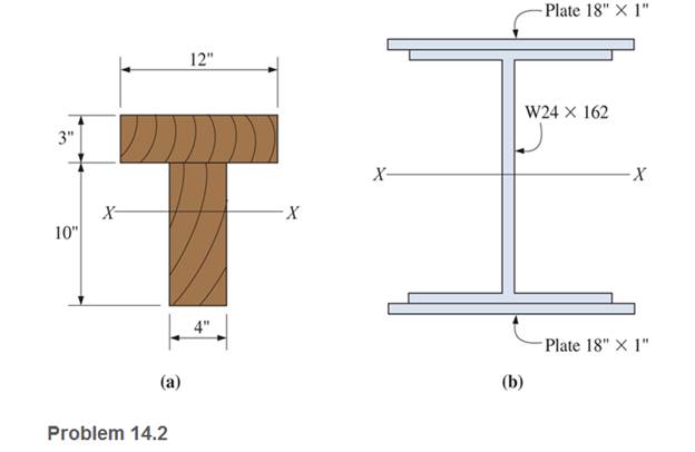
Chapter 14, Problem 14.2P
Calculate the section modulus (with respect to the X-X axis) for the beams shown.
Expert Solution & Answer

Trending nowThis is a popular solution!

Learn your wayIncludes step-by-step video

schedule03:46
Students have asked these similar questions
The figure below shows the cross-section of an axisymmetric composite beam that
comprises steel (Young's modulus 270 GPa) and aluminum (Young's modulus 90 GPa)
sections that are bonded together.
The steel section is of wall thickness 15 mm and the aluminum section is of wall thickness
10mm. The steel section comprises 4 axisymmetric holes of 5 mm diameter as shown.
Given that the beam is bent by a couple moment of 1200 Nm, determine the maximum
stress in steel and aluminum.
4 holes of diameter 5 mm.
12 mm
steel
aluminum
Find the torsion constant of the following beam cross section.
Modulus E of elasticity, for the ACB beam with inertia I;
a- Find the elastic curve equation with the singularity equation.
b- Find the reaction forces at Point A.
c- Find the reaction force at Point B.
(2/3) W
2W
A
W
-L/2
L
Chapter 14 Solutions
Applied Statics and Strength of Materials (6th Edition)
Ch. 14 - Calculate the section modulus for: (a) a 6 -in-by-...Ch. 14 - Calculate the section modulus (with respect to the...Ch. 14 - Prob. 14.3PCh. 14 - Rework Problem 14.3 changing the orientation of...Ch. 14 - Assume that the timber member (a) of Problem 14.2...Ch. 14 - The structural steel built-up member (b) of...Ch. 14 - A round steel rod, 25 mm in diameter, is subjected...Ch. 14 - A square steel bar, 38 mm on each side, is used as...Ch. 14 - Calculate the moment strength for a W36302...Ch. 14 - Calculate the allowable bending moment for a solid...
Ch. 14 - The beams of cross sections shown are subjected to...Ch. 14 - A solid rectangular simply supported timber beam 6...Ch. 14 - A W1430 supports the loads shown. Calculate the...Ch. 14 - If the allowable shear stress is 100 MPa,...Ch. 14 - A steel pin 112 in diameter is subjected to a...Ch. 14 - A timber power-line pole is 10 in. in diameter at...Ch. 14 - Calculate the value of S and Z and the shape...Ch. 14 - For beams that have cross sections as shown for...Ch. 14 - Calculate the maximum load P that the beam shown...Ch. 14 - A 412 (S4S) hem-fir timber beam carries a...Ch. 14 - A simply supported W1636 A992 steel beam carries a...Ch. 14 - A W250115 steel wide-flange section supports a...Ch. 14 - Assume that the floor joist dimensions of Example...Ch. 14 - Calculate the allowable superimposed uniformly...Ch. 14 - A 3 -in.-by- 12 -in. (S4S) scaffold timber plank...Ch. 14 - For the following computer problems, any...Ch. 14 - For the following computer problems, any...Ch. 14 - For the following computer problems, any...Ch. 14 - Calculate the section modulus with respect to the...Ch. 14 - The timber box section (a) of Problem 14.29 is...Ch. 14 - A timber beam is subjected to a maximum bending...Ch. 14 - Rework Problem 14.31 assuming that the beam is...Ch. 14 - A 12 -in.-diameter steel rod projects 2 ft...Ch. 14 - Calculate the maximum bending stress in a W530101...Ch. 14 - A cantilever cast-iron beam is 6 ft long and has a...Ch. 14 - 14.36 Calculate the moment strength for a...Ch. 14 - A W813 steel wide-flange beam on a 20 -ft span is...Ch. 14 - A simply supported beam with a cruciform cross...Ch. 14 - A rectangular beam 100 mm in width and 250 mm in...Ch. 14 - The timber box section (a) of Problem 14.29 is...Ch. 14 - For the I-shaped timber beam shown, calculate the...Ch. 14 - 14.42 A steel wide-flange beam is oriented so that...Ch. 14 - A W1045steel wide-flange beam supports a uniformly...Ch. 14 - 14.44 A steel wide-flange section is subjected to...Ch. 14 - A W30108 steel wide-flange beam is simply...Ch. 14 - A W612 is strengthened with a 34 -in.-by- 34 -in....Ch. 14 - Four wood boards 1 in. by 6 in. in cross section...Ch. 14 - A lintel consists of two 8 -in.-by- 12 in. steel...Ch. 14 - A 50 -mm-by- 300 -mm scaffold timber plank, placed...Ch. 14 - A laminated wood beam is built up by gluing...Ch. 14 - A rectangular hollow shape carries loads as shown....Ch. 14 - For the beam shown, calculate the maximum tensile...Ch. 14 - 14.53 A box beam is built up of four -in.-by--in....Ch. 14 - 14.54 Find the value of the loads P that can be...Ch. 14 - 14.55 Solve Problem 14.54 assuming that the timber...Ch. 14 - Calculate the values of S and Z and the shape...Ch. 14 - 14.57 A is supported on simple supports on a -ft...
Additional Engineering Textbook Solutions
Find more solutions based on key concepts
In each case, determine the moment of the force about point O. Prob. P3-1
Statics and Mechanics of Materials (5th Edition)
What parts are included in the vehicle chassis?
Automotive Technology: Principles, Diagnosis, and Service (5th Edition)
The force in members BC, CF, and FE of the truss and the state of members are in tension or compression.
Engineering Mechanics: Statics & Dynamics (14th Edition)
Determine the largest load P that can be applied to the frame without causing either the average normal stress ...
Mechanics of Materials
45. A box has a volume of 10 gallons [gal]. If two sides of the box measure 2.4 meters [m] by 2.4 feet [ft], wh...
Thinking Like an Engineer: An Active Learning Approach (4th Edition)
Resolve each force acting on the post into its x and y components. Prob. F2-7
Engineering Mechanics: Statics
Knowledge Booster


Learn more about
Need a deep-dive on the concept behind this application? Look no further. Learn more about this topic, mechanical-engineering and related others by exploring similar questions and additional content below.Similar questions
- please do it correctly and neatlyarrow_forwardThe figure below shows two solid homogenous rectangular beam sections with (breadth x depth) dimensions in two different orientations as follows: Beam Section Orientation A (t mm x 2t mm); and Beam Section Orientation B (2t mm x tmm). Both beams sag when subjected to the same loading and support conditions resulting in compressive stresses above the centroid line (neutral axis). Which statement accurately describes the relative maximum compressive stress (ocompression) between these beam section orientations? O a. O b. Oc tmm 2 mm Beam Section Orientation A 2tmm 7 mm Beam Section Orientation B Maximum compressive stress (compression) in orientation B is greater than orientation A by a factor of 2. Maximum compressive stress (ocompression) in orientation A is greater than orientation B by a factor of 4. Maximum compressive stress (compression) in orientation B is greater than orientation A by a factor of 4. O d. Maximum compressive stress (ocompression) in orientation A is greater than…arrow_forwardFirst image is question one.arrow_forward
- The figure below shows two solid homogenous rectangular beam sections with (breadth x depth) dimensions in two different orientations as follows: Beam Section Orientation A (t mm x 2t mm); and Beam Section Orientation B (2t mm xt mm). Both beams sag when subjected to the same loading and support conditions resulting in compressive stresses above the centroid line (neutral axis). Which statement accurately describes the relative maximum compressive stress (ocompression) between these beam section orientations? * Maximum compressive stress (acompression) in orientation A is greater than orientation B by a factor of 4. Maximum compressive stress (acompression) in orientation B is greater than orientation A by a factor of 4. * Maximum compressive stress (acompression) in orientation B is greater than orientation A by a factor of 2. 4 Maximum compressive stress (acompression) in orientation A is greater than orientation B by a factor of 2.arrow_forwardFor the beam I-section below, calculate the second moment of area about its centroidal y-axis (Iyycentroid). Give your answer in m4 to 2 significant figures (not mm4). 120 mm 75 mm 425 mm 50 mm- y 150 mm 400 mm X Answer:arrow_forwardPlease answer neatlyarrow_forward
- A beam has a bending moment of 3.5 kN-m applied to a section with a hollow circular cross-section of external diameter 3.6 cm and internal diameter 2.4 cm . The modulus of elasticity for the material is 210 x 109 N/m2. Calculate the radius of curvature and maximum bending stress. Also, calculate the stress at the point at 0.5 cm from the neutral axis (i) The moment of inertia = ii) The radius of curvature is (iii) The maximum bending stress is iv) The bending stress at the point 0.5 cm from the neutral axis isarrow_forward3. Determine the displacement and slope (i.e. 0) at the load point for the stepped beam shown in the following figure. Also determine the reaction forces and moments. Each element has E = 200 GPa. The area moment of inertia are given as I₁ = 1.25 × 105 mm4, and 2 = 4 x 104 mm. Clearly show the elemental stiffness matrices (k) for each element, assembly of k matrices to get global stiffness matrix (K) and application of boundary conditions. Then solve the reduced K matrix to get displacements and reactions 3000 N 150 mm 75 mm 125 mmarrow_forward3. Two beams are supported as shown in the diagram below, each 150mm x 200mm x 6 meters. Beam CD is a cantilever beam carrying a uniformly distributed load of 6 KN/m freely supported on beam AB. Beam AB is freely supported on each ends. E = 13.8 GPa for both beam. Neglect the weight of the beam. a. Compute the reaction at D. b. Compute the deflection at D. c. Compute the bending stress of beam CD. 6 ka lm бт 6m 6marrow_forward
- A beam has a bending moment of 3.5 kN-m applied to a section with a hollow circular cross-section of external diameter 3.7 cm and internal diameter 2.2 cm . The modulus of elasticity for the material is 210 x 109 N/m2. Calculate the radius of curvature and maximum bending stress. Also, calculate the stress at the point at 0.6 cm from the neutral axis (i) The moment of inertia = ii) The radius of curvature is (iii) The maximum bending stress is iv) The bending stress at the point 0.6 cm from the neutral axis is Answer and unit for part 4arrow_forwardQ3a For the beam l-section below, calculate the second moment of area about its centroidal x-axis (Ixxcentroid). Give your answer in m4 to 2 significant figures (not mm“). 120 mm 75 mm 425 mm 50 mm- y 150 mm 400 mmarrow_forwardA uniform beam is fixed at end x=0 and simply supported at x = L. Find the shape of the center line of the beam, given the weight per unit Length is w. a. b. C. e. O y(x) = d. y(x) = a y(x) = y(x) = y(x) = W 24 El -[x4 - 4Lx³ +6L²x²] =[x4-2Lx³ + L²x²] -[x4-2Lx³ + L³x] -[2x4-5Lx³+3L²x²] [2x4-3L³x³ +3L²x²] W 24 El W 24 El W 24 El - W 24 EIarrow_forward
arrow_back_ios
SEE MORE QUESTIONS
arrow_forward_ios
Recommended textbooks for you
 Mechanics of Materials (MindTap Course List)Mechanical EngineeringISBN:9781337093347Author:Barry J. Goodno, James M. GerePublisher:Cengage Learning
Mechanics of Materials (MindTap Course List)
Mechanical Engineering
ISBN:9781337093347
Author:Barry J. Goodno, James M. Gere
Publisher:Cengage Learning
Understanding Shear Force and Bending Moment Diagrams; Author: The Efficient Engineer;https://www.youtube.com/watch?v=C-FEVzI8oe8;License: Standard YouTube License, CC-BY
Bending Stress; Author: moodlemech;https://www.youtube.com/watch?v=9QIqewkE6xM;License: Standard Youtube License