
Concept explainers
Videos
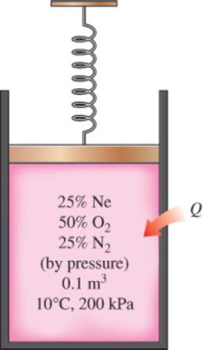
A spring-loaded piston–cylinder device contains a mixture of gases whose pressure fractions are 25 percent Ne, 50 percent O2, and 25 percent N2. The piston diameter and spring are selected for this device such that the volume is 0.1 m3 when the pressure is 200 kPa and 1.0 m3 when the pressure is 1000 kPa. Initially, the gas is added to this device until the pressure is 200 kPa and the temperature is 10°C. The device is now heated until the pressure is 500 kPa. Calculate the total work and heat transfer for this process.
The total work done and heat transfer for the process.
Answer to Problem 93RP
The total work done for the process is
The heat transfer for the process is
Explanation of Solution
Write the expression to calculate the partial pressure of
Here, mixture pressure is
Write the expression to calculate the partial pressure of
Here, mixture pressure is
Write the expression to calculate the partial pressure of
Here, mixture pressure is
Write the expression to calculate the mass of
Write the expression to calculate the mass of
Write the expression to calculate the mass of
Write the expression to calculate the total mass of each component
Write the expression to calculate the mass fraction of
Write the expression to calculate the mass fraction of
Write the expression to calculate the mass fraction of
Write the expression to calculate the mole number of
Here, molar mass of
Write the expression to calculate the mole number of
Here, molar mass of
Write the expression to calculate the mole number of
Here, molar mass of
Write the expression to calculate the total number of moles
Write the expression to calculate the apparent molecular weight of the mixture
Write the expression to calculate the constant volume specific heat of the mixture
Here, mole fraction of
Write the expression to calculate the apparent gas constant of the mixture
Here, universal gas constant is
Write the expression for the mass contained in the system
Write the expression to calculate the final temperature
Write the expression to calculate the work done during the process.
Conclusion:
From Table A-1, “Molar mass, gas constant, and critical point properties”, obtain the values of molar masses for
From Table A-2a, “Ideal-gas specific heats of various common gases”, obtain the following properties for
For
For
For
Substitute
Substitute
Substitute
Substitute
Substitute
Substitute
Substitute
Substitute
Substitute
Substitute
Substitute
Substitute
Substitute
Substitute
Substitute
Substitute
Substitute
Substitute
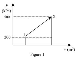
The pressure changes linearly with volume as shown is Figure (1).
Using the data form Prob. 13–94 obtain the value of final volume by linear interpolation.
Write the straight line equation for two points.
Here, coordinates of the point 1 is
Substitute
The final volume
Substitute
Substitute
Thus, the total work done for the process is
Write a energy balance on the system.
Here, input energy transfer and output energy transfer is
The rate of change in energy of a system
For given system the energy balance Equation (XXII) is expressed as follows:
The rate of change in energy of a system
Substitute
Thus, the heat transfer for the process is
Want to see more full solutions like this?
Chapter 13 Solutions
THERMODYNAMICS(SI UNITS,INTL.ED)EBOOK>I


- The gears shown in the figure have a diametral pitch of 2 teeth per inch and a 20° pressure angle. The pinion rotates at 1800 rev/min clockwise and transmits 200 hp through the idler pair to gear 5 on shaft c. What forces do gears 3 and 4 transmit to the idler shaft? TS I y 18T 32T This a 12 x 18T C 48T 5arrow_forwardQuestion 1. Draw 3 teeth for the following pinion and gear respectively. The teeth should be drawn near the pressure line so that the teeth from the pinion should mesh those of the gear. Drawing scale (1:1). Either a precise hand drawing or CAD drawing is acceptable. Draw all the trajectories of the involute lines and the circles. Specification: 18tooth pinion and 30tooth gear. Diameter pitch=P=6 teeth /inch. Pressure angle:20°, 1/P for addendum (a) and 1.25/P for dedendum (b). For fillet, c=b-a.arrow_forward5. The figure shows a gear train. There is no friction at the bearings except for the gear tooth forces. The material of the milled gears is steel having a Brinell hardness of 170. The input shaft speed (n2) is 800 rpm. The face width and the contact angle for all gears are 1 in and 20° respectively. In this gear set, the endurance limit (Se) is 15 kpsi and nd (design factor) is 2. (a) Find the revolution speed of gear 5. (b) Determine whether each gear satisfies the design factor of 2.0 for bending fatigue. (c) Determine whether each gear satisfies the design factor of 2.0 for surface fatigue (contact stress). (d) According to the computation results of the questions (b) and (c), explain the possible failure mechanisms for each gear. N4=28 800rpm N₁=43 N5=34 N₂=14 P(diameteral pitch)=8 for all gears Coupled to 2.5hp motorarrow_forward
- 1. The rotating steel shaft is simply supported by bearings at points of B and C, and is driven by a spur gear at D, which has a 6-in pitch diameter. The force F from the drive gear acts at a pressure angle of 20°. The shaft transmits a torque to point A of TA =3000 lbĘ in. The shaft is machined from steel with Sy=60kpsi and Sut=80 kpsi. (1) Draw a shear force diagram and a bending moment diagram by F. According to your analysis, where is the point of interest to evaluate the safety factor among A, B, C, and D? Describe the reason. (Hint: To find F, the torque Tд is generated by the tangential force of F (i.e. Ftangential-Fcos20°) When n=2.5, K=1.8, and K₁ =1.3, determine the diameter of the shaft based on (2) static analysis using DE theory (note that fatigue stress concentration factors need to be used for this question because the loading condition is fatigue) and (3) a fatigue analysis using modified Goodman. Note) A standard diameter is not required for the questions. 10 in Darrow_forward3 N2=28 P(diametral pitch)=8 for all gears Coupled to 25 hp motor N3=34 Full depth spur gears with pressure angle=20° N₂=2000 rpm (1) Compute the circular pitch, the center-to-center distance, and base circle radii. (2) Draw the free body diagram of gear 3 and show all the forces and the torque. (3) In mounting gears, the center-to-center distance was reduced by 0.1 inch. Calculate the new values of center-to-center distance, pressure angle, base circle radii, and pitch circle diameters. (4)What is the new tangential and radial forces for gear 3? (5) Under the new center to center distance, is the contact ratio (mc) increasing or decreasing?arrow_forward2. A flat belt drive consists of two 4-ft diameter cast-iron pulleys spaced 16 ft apart. A power of 60 hp is transmitted by a pulley whose speed is 380 rev/min. Use a service factor (Ks) pf 1.1 and a design factor 1.0. The width of the polyamide A-3 belt is 6 in. Use CD=1. Answer the following questions. (1) What is the total length of the belt according to the given geometry? (2) Find the centrifugal force (Fc) applied to the belt. (3) What is the transmitted torque through the pulley system given 60hp? (4) Using the allowable tension, find the force (F₁) on the tight side. What is the tension at the loose side (F2) and the initial tension (F.)? (5) Using the forces, estimate the developed friction coefficient (f) (6) Based on the forces and the given rotational speed, rate the pulley set. In other words, what is the horse power that can be transmitted by the pulley system? (7) To reduce the applied tension on the tight side, the friction coefficient is increased to 0.75. Find out the…arrow_forward
- The tooth numbers for the gear train illustrated are N₂ = 24, N3 = 18, №4 = 30, №6 = 36, and N₁ = 54. Gear 7 is fixed. If shaft b is turned through 5 revolutions, how many turns will shaft a make? a 5 [6] barrow_forwardCE-112 please solve this problem step by step and give me the correct answerarrow_forwardCE-112 please solve this problem step by step and give me the correct answerarrow_forward
- CE-112 solve this problem step by step and give me the correct answer pleasearrow_forwardPlease do not use any AI tools to solve this question. I need a fully manual, step-by-step solution with clear explanations, as if it were done by a human tutor. No AI-generated responses, please.arrow_forwardPlease do not use any AI tools to solve this question. I need a fully manual, step-by-step solution with clear explanations, as if it were done by a human tutor. No AI-generated responses, please.arrow_forward
 Refrigeration and Air Conditioning Technology (Mi...Mechanical EngineeringISBN:9781305578296Author:John Tomczyk, Eugene Silberstein, Bill Whitman, Bill JohnsonPublisher:Cengage Learning
 Principles of Heat Transfer (Activate Learning wi...Mechanical EngineeringISBN:9781305387102Author:Kreith, Frank; Manglik, Raj M.Publisher:Cengage Learning
 International Edition---engineering Mechanics: St...Mechanical EngineeringISBN:9781305501607Author:Andrew Pytel And Jaan KiusalaasPublisher:CENGAGE L