
(a)
The small signal differential-mode voltage gain.
(a)
Answer to Problem 13.5P
The overall small signal differential voltage gain
Explanation of Solution
Given:
The circuit diagram of the BJT op-amp is

Given that
The transistor parameters are,
And base-emitter turn-on voltage is
Calculation:
The differential mode voltage gain can be defined as
Where
From the figure the quiescent collector currents in
Hence,
The collector current for
Therefore, the collector current for
The transconductance can be calculated as
Therefore, the transconductance for
The resistance
Therefore, the resistance
The resistance
Therefore, the resistance
The resistance
Therefore, the resistance
The resistance
Therefore, the resistance
Substitute
Hence,
Substitute
Therefore, the differential mode voltage gain
The small signal voltage gain is

Now,
Therefore,
Where the resistance
Hence,
Equation(2) becomes
Therefore, the small signal voltage gain is
Now the overall small signal differential voltage gain is
Therefore, the overall small signal differential voltage gain
(b)
The differential-mode input resistance.
(b)
Answer to Problem 13.5P
The differential-mode input resistance is
Explanation of Solution
Given:
The circuit diagram of the BJT op-amp is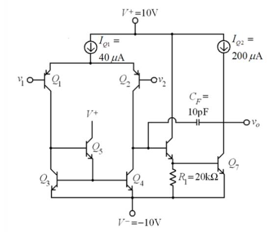
Given that
The transistor parameters are,
And base-emitter turn-on voltage is
Calculation:
The differential-mode input resistance is given as
Where
Hence,
Now, the differential-mode input resistance is
Therefore, the differential-mode input resistance is
(c)
Theunity-gain bandwidth.
(c)
Answer to Problem 13.5P
The gain bandwidth product is
Explanation of Solution
Given:
The circuit diagram of the BJT op-amp is

Given that
The transistor parameters are,
And base-emitter turn-on voltage is
Calculation:
The unity-gain bandwidth product is
Here, the dominant pole frequency is given as
Hence,
And
Hence,
Now the dominant pole frequency we obtain as
Therefore, the dominant pole frequency
The unity-gain bandwidth product is
Therefore, the gain bandwidth product is
Want to see more full solutions like this?
Chapter 13 Solutions
Microelectronics: Circuit Analysis and Design

- The joint density function of two continuous random variables X and Yis: p(x, y) = {Keós (x + y) Find (i) the constant K 0 2 0arrow_forwardShow all the steps please, Solve for the current through R2 if E2 is replaced by a current source of 10mA using superposition theorem. R5=470Ω R2=1000Ω R6=820Ωarrow_forwardPlease solve it by explaining the steps. I am trying to prepare for my exam tomorrow, so any tips and tricks to solve similar problems are highly appreciated. Plus, this is a past exam I am using to prepare.arrow_forwardPlease solve it by explaining the steps. I am trying to prepare for my exam today, so any tips and tricks to solve similar problems are highly appreciated. Plus, this is a past exam I am using to prepare.arrow_forwardIf C is the circle |z|=4 evaluate f f (z)dz for each of the following functions using residue. 1 f(z) = z(z²+6z+4)arrow_forwardIf C is the circle |z|=4 evaluate ff(z)dz for each of the following functions using residue. f(z) z(z²+6z+4)arrow_forwardDetermine X(w) for the given function shown in Figure (1) by applying the differentiation property of the Fourier Transform. 1 x(t) Figure (1) -2 I -1 1 2arrow_forwardPlease solve it by explaining the steps. I am trying to prepare for my exam tomorrow, so any tips and tricks to solve similar problems are highly appreciated. Plus, this is a past exam I am using to prepare.arrow_forwardPlease solve it by explaining the steps. I am trying to prepare for my exam tomorrow, so any tips and tricks to solve similar problems are highly appreciated. Plus, this is a past exam I am using to prepare.arrow_forwardPlease solve it by explaining the steps. I am trying to prepare for my exam tomorrow, so any tips and tricks to solve similar problems are highly appreciated. Plus, this is a past exam I am using to prepare.arrow_forwardPlease solve it by explaining the steps. I am trying to prepare for my exam tomorrow, so any tips and tricks to solve similar problems are highly appreciated. Plus, this is a past exam I am using to prepare.arrow_forwardPlease solve it by explaining the steps. I am trying to prepare for my exam tomorrow, so any tips and tricks to solve similar problems are highly appreciated. Plus, this is a past exam I am using to prepare.arrow_forwardarrow_back_iosSEE MORE QUESTIONSarrow_forward_ios
 Introductory Circuit Analysis (13th Edition)Electrical EngineeringISBN:9780133923605Author:Robert L. BoylestadPublisher:PEARSON
 Delmar's Standard Textbook Of ElectricityElectrical EngineeringISBN:9781337900348Author:Stephen L. HermanPublisher:Cengage Learning
 Programmable Logic ControllersElectrical EngineeringISBN:9780073373843Author:Frank D. PetruzellaPublisher:McGraw-Hill Education
 Fundamentals of Electric CircuitsElectrical EngineeringISBN:9780078028229Author:Charles K Alexander, Matthew SadikuPublisher:McGraw-Hill Education
 Electric Circuits. (11th Edition)Electrical EngineeringISBN:9780134746968Author:James W. Nilsson, Susan RiedelPublisher:PEARSON
 Engineering ElectromagneticsElectrical EngineeringISBN:9780078028151Author:Hayt, William H. (william Hart), Jr, BUCK, John A.Publisher:Mcgraw-hill Education,