
Applied Statics and Strength of Materials (6th Edition)
6th Edition
ISBN: 9780133840544
Author: George F. Limbrunner, Craig D'Allaird, Leonard Spiegel
Publisher: PEARSON
expand_more
expand_more
format_list_bulleted
Concept explainers
Videos
Textbook Question
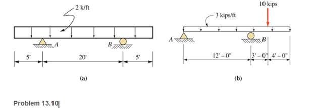
Chapter 13, Problem 13.10P
Calculate the shear and bending moment at 5 ft and at 15 ft from the left for the beams shown. Show free-body diagrams.
Expert Solution & Answer

Learn your wayIncludes step-by-step video

schedule09:27
Students have asked these similar questions
Draw the shear and bending-moment diagrams for the simply sup-ported beam shown in Fig. and determine the maximum value of the bending moment
For the following beams shown,
(1) Derive the shear force and bending moment equations; and
(2) draw the shear force and bending moment diagrams. Neglect the weight of the beam.
I'm on my last attempt pls help
Chapter 13 Solutions
Applied Statics and Strength of Materials (6th Edition)
Ch. 13 - through 13.6 Calculate the reactions at points A...Ch. 13 - Calculate the reactions at points A and B for the...Ch. 13 - through 13.6 Calculate the reactions at points A...Ch. 13 - Calculate the reactions at points A and B for the...Ch. 13 - Calculate the reactions at points A and B for the...Ch. 13 - Calculate the reactions at points A and B for the...Ch. 13 - Calculate the shear and bending moment at 4 m and...Ch. 13 - Calculate the shear and bending moment at 3 ft and...Ch. 13 - Calculate the shear and bending moment at midspan...Ch. 13 - Calculate the shear and bending moment at 5 ft and...
Ch. 13 - Calculate the shear and bending moment at 5 m and...Ch. 13 - For the beams shown, draw complete shear diagrams.Ch. 13 - For the beams shown, draw complete shear diagrams.Ch. 13 - Prob. 13.14PCh. 13 - For the beams shown, draw complete shear diagrams.Ch. 13 - For the beams shown (next page), draw complete...Ch. 13 - For the beams shown (next page), draw complete...Ch. 13 - For the beams shown (next page), draw complete...Ch. 13 - For the beams shown (next page), draw complete...Ch. 13 - For the beams shown (next page), draw complete...Ch. 13 - For the beams shown, draw complete shear and...Ch. 13 - For the beams shown, draw complete shear and...Ch. 13 - For the beams shown, draw complete shear and...Ch. 13 - A moving-load system is composed of two...Ch. 13 - A moving-load system is composed of two...Ch. 13 - One of the standard truck loads used in the design...Ch. 13 - Write a computer program that will calculate the...Ch. 13 - Write a program that will calculate the shear and...Ch. 13 - Viking Consultants wishes to generate a table of...Ch. 13 - Calculate the reactions for the simple beams...Ch. 13 - Calculate the reactions for the overhanging beams...Ch. 13 - Calculate the reactions at points A and B for the...Ch. 13 - Calculate the reactions at points A and B for the...Ch. 13 - For the beams of Problem 13.33, calculate the...Ch. 13 - For the beam shown, calculate the shear and...Ch. 13 - Calculate the shear and bending moment at points 4...Ch. 13 - Calculate the shear arid bending moment at points...Ch. 13 - Calculate the shear and bending moment at points...Ch. 13 - Refer to the beam shown and draw complete shear...Ch. 13 - Refer to the beam shown and draw complete shear...Ch. 13 - Refer to the beam shown and draw complete shear...Ch. 13 - Refer to the beam shown and draw complete shear...Ch. 13 - Refer to the beam shown and draw complete shear...Ch. 13 - Refer to the beam shown and draw complete shear...Ch. 13 - Refer to the beam shown and draw complete shear...Ch. 13 - Refer to the beam shown and draw complete shear...Ch. 13 - Refer to the beam shown and draw complete shear...Ch. 13 - Refer to the indicated problem and draw complete...Ch. 13 - Refer to the indicated problem and draw complete...Ch. 13 - Refer to the indicated problem and draw complete...Ch. 13 - Refer to the indicated problem and draw complete...Ch. 13 - Refer to the indicated problem and draw complete...Ch. 13 - Refer to the indicated problem and draw complete...Ch. 13 - Refer to the indicated problem and draw complete...Ch. 13 - Refer to the indicated problem and draw complete...Ch. 13 - Refer to the indicated problem and draw complete...Ch. 13 - Refer to the indicated problem and draw complete...Ch. 13 - Refer to the indicated problem and draw complete...Ch. 13 - A two-axle roller with axles 5 m apart passes over...Ch. 13 - A moving load system with wheels at fixed...Ch. 13 - A moving-load system with wheels spaced as shown...
Additional Engineering Textbook Solutions
Find more solutions based on key concepts
44. How large a surface area in units of square feet [ft2] will 1 gallon [gal] of paint cover if we apply a coa...
Thinking Like an Engineer: An Active Learning Approach (4th Edition)
For the compound differential manometer in Fig.3.32, calculate (pA-pB
Applied Fluid Mechanics (7th Edition)
The two cylindrical rod segments are fixed to the rigid walls such that there is a gap of 0.01 in. between them...
Mechanics of Materials (10th Edition)
If the 30-kg disk is released from rest when = 0 , determine its angular velocity when = 90.
Engineering Mechanics: Dynamics (14th Edition)
Determine the couple moment acting on the beam.
INTERNATIONAL EDITION---Engineering Mechanics: Statics, 14th edition (SI unit)
The force applied at the handle of the rigid lever causes the lever to rotate clockwise about the pin B through...
Statics and Mechanics of Materials (5th Edition)
Knowledge Booster


Learn more about
Need a deep-dive on the concept behind this application? Look no further. Learn more about this topic, mechanical-engineering and related others by exploring similar questions and additional content below.Similar questions
- problemarrow_forwardBOX THE ANSWER. PUT A FREE BODY DIAGRAM. THANK YOUarrow_forwardDraw the shear force and bending moment diagrams for the beam shown in your solution sheets. Determine the maximum positive shear force in kips. Determine the maximum negative shear force in kips. Determine the maximum positive bending moment in kip-ft. Determine the maximum negative bending moment in kip-ft.* Determine the point of inflection from point C in feet.arrow_forward
- Write shear and moment equations for the beam loaded as shown in figure below. Also, draw shear and moment diagrams, specifying values at all change of loading positions and at points of zeron shear. Neglect the mass of the beam.arrow_forwardWhen loads and moments are applied to the cantilever beam as shown in the picture below, draw the shear and bending moment lines.arrow_forward(a) derive equations for the shear force V and the bending momentM for any location in the beam. (Place the origin at point A.)(b) use the derived functions to plot the shear-force and bendingmomentdiagrams for the beam.(c) specify the values for key points on the diagrams.arrow_forward
- (a) derive equations for the shear force V and the bending moment M for any location in the beam. Place the origin at point A.) (b) use the derived functions to plot the shear-force and bending-moment diagrams for the beam. Specify the values for key points on the diagrams. Wo A Larrow_forwardCalculate the bending moment at points A and B for the beam shown below. 5 kN 2.5 kN/m A 1.5 m 4 marrow_forwardBOX THE ANSWER. PUT A FREE BODY DIAGRAM. THANK YOUarrow_forward
- Use the graphical method to construct the shearforceand bending-moment diagrams for the beams shown in Figurebelow. Label all significant points on each diagram, andidentify the maximum moments (both positive and negative) alongwith their respective locations. Clearly differentiate straight-lineand curved portions of the diagrams.arrow_forwardFor the following beams shown, (1) Derive the shear force and bending moment equations; and (2) draw the shear force and bending moment diagrams. Neglect the weight of the beam.arrow_forwardFor the beam shown, the magnitude of the distributed load is wo = 11.8 kN/m and the beam length is L = 7.9 m. (a) derive equations for the shear force Vand the bending moment M for any location in the beam. Place the origin at point A. (b) use the derived functions to plot the shear-force and bending-moment diagrams for the beam. Use your diagrams to determine the maximum shear force and maximum bending moment. Note that answers may be positive or negative. Here, "maximum" refers to the largest magnitude value, but you should enter your shear force and bending moment with the correct sign, using the sign convention presented in Section 7.2 of the textbook. If the magnitudes of the largest positive and largest negative values are the same, enter a positive number. Wo A В L. Answer: Vmax = kN Mmax kN•marrow_forward
arrow_back_ios
SEE MORE QUESTIONS
arrow_forward_ios
Recommended textbooks for you
 Elements Of ElectromagneticsMechanical EngineeringISBN:9780190698614Author:Sadiku, Matthew N. O.Publisher:Oxford University Press
 Mechanics of Materials (10th Edition)Mechanical EngineeringISBN:9780134319650Author:Russell C. HibbelerPublisher:PEARSON
 Thermodynamics: An Engineering ApproachMechanical EngineeringISBN:9781259822674Author:Yunus A. Cengel Dr., Michael A. BolesPublisher:McGraw-Hill Education
 Control Systems EngineeringMechanical EngineeringISBN:9781118170519Author:Norman S. NisePublisher:WILEY
 Mechanics of Materials (MindTap Course List)Mechanical EngineeringISBN:9781337093347Author:Barry J. Goodno, James M. GerePublisher:Cengage Learning
 Engineering Mechanics: StaticsMechanical EngineeringISBN:9781118807330Author:James L. Meriam, L. G. Kraige, J. N. BoltonPublisher:WILEY
Elements Of Electromagnetics
Mechanical Engineering
ISBN:9780190698614
Author:Sadiku, Matthew N. O.
Publisher:Oxford University Press
Mechanics of Materials (10th Edition)
Mechanical Engineering
ISBN:9780134319650
Author:Russell C. Hibbeler
Publisher:PEARSON
Thermodynamics: An Engineering Approach
Mechanical Engineering
ISBN:9781259822674
Author:Yunus A. Cengel Dr., Michael A. Boles
Publisher:McGraw-Hill Education
Control Systems Engineering
Mechanical Engineering
ISBN:9781118170519
Author:Norman S. Nise
Publisher:WILEY
Mechanics of Materials (MindTap Course List)
Mechanical Engineering
ISBN:9781337093347
Author:Barry J. Goodno, James M. Gere
Publisher:Cengage Learning
Engineering Mechanics: Statics
Mechanical Engineering
ISBN:9781118807330
Author:James L. Meriam, L. G. Kraige, J. N. Bolton
Publisher:WILEY
Understanding Shear Force and Bending Moment Diagrams; Author: The Efficient Engineer;https://www.youtube.com/watch?v=C-FEVzI8oe8;License: Standard YouTube License, CC-BY
Bending Stress; Author: moodlemech;https://www.youtube.com/watch?v=9QIqewkE6xM;License: Standard Youtube License