
Concept explainers
through 13.6 Calculate the reactions at points A and BFor the beams shown.
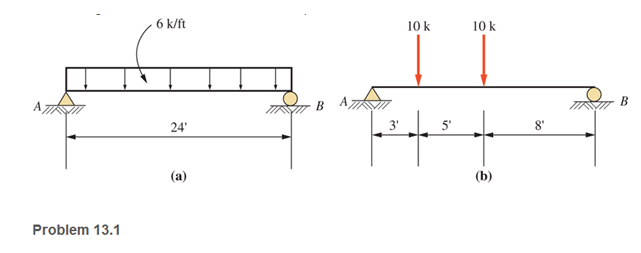
a.
The reaction forces at points A and B
Answer to Problem 13.1P
Explanation of Solution
Given:
The beam diagram and loading are given as shown below:
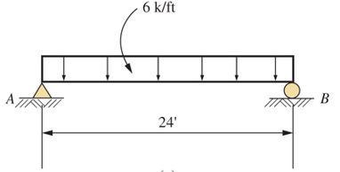
Concept Used:
Replacing the uniformly distribute load by a concentrated external load
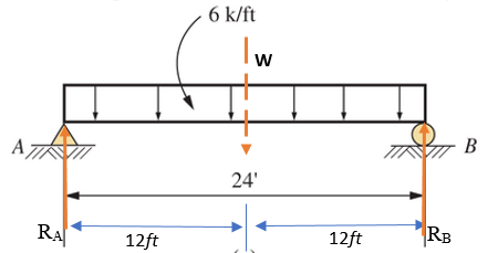
Calculation:
Taking anticlockwise moment positive, the summation of all moment of forces at point A equals to zero
For vertical equilibrium, the summation of forces in vertical direction must be zero
Conclusion:
Therefore, the reaction force at points A,
b.
The reaction forces at points A and B
Answer to Problem 13.1P
Explanation of Solution
Given:
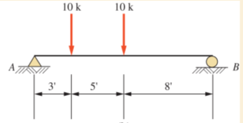
The beam diagram and loading are given as shown below
Concept Used:
The reaction forces at point A and B are shown below in the figure and assumed to act in the upward (positive) direction
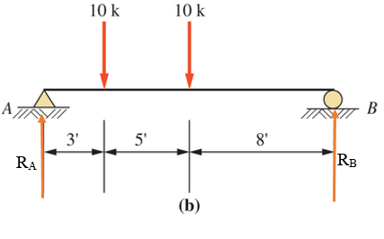
Calculation:
Taking anticlockwise moment positive, the summation of all moment of forces at point A equals to zero
For vertical equilibrium, the summation of forces in vertical direction must be zero
Conclusion:
Therefore, the forces are
Want to see more full solutions like this?
Chapter 13 Solutions
Applied Statics and Strength of Materials (6th Edition)
Additional Engineering Textbook Solutions
Web Development and Design Foundations with HTML5 (8th Edition)
Modern Database Management
Mechanics of Materials (10th Edition)
Starting Out with Java: From Control Structures through Data Structures (4th Edition) (What's New in Computer Science)
Starting Out with C++ from Control Structures to Objects (9th Edition)
Thinking Like an Engineer: An Active Learning Approach (4th Edition)
- Please do not use any AI tools to solve this question. I need a fully manual, step-by-step solution with clear explanations, as if it were done by a human tutor. No AI-generated responses, please.arrow_forwardPlease do not use any AI tools to solve this question. I need a fully manual, step-by-step solution with clear explanations, as if it were done by a human tutor. No AI-generated responses, please.arrow_forwardCE-112 please solve this problem step by step and give me the correct answerarrow_forward
- CE-112 please solve this problem step by step and give me the correct asnwerarrow_forwardthis is an old practice exam, the answer is Ax = -4, Ay = -12,Az = 32.5, Bx= 34, Bz = 5, By = 0 but how?arrow_forwardThis is an old practice exam, the answer is Ax = Az = 0, Ay = 2000, TDE = 4750, Cx = 2000, Cy = 2000, Cz = -800 but how?arrow_forward
- this is an old practice exam, the answer is Fmin = 290.5lb but howarrow_forwardThis is an exam review question. The answer is Pmin = 622.9 lb but whyarrow_forwardPlease do not use any AI tools to solve this question. I need a fully manual, step-by-step solution with clear explanations, as if it were done by a human tutor. No AI-generated responses, please.arrow_forward
- Please do not use any AI tools to solve this question. I need a fully manual, step-by-step solution with clear explanations, as if it were done by a human tutor. No AI-generated responses, please.arrow_forwardPlease do not use any AI tools to solve this question. I need a fully manual, step-by-step solution with clear explanations, as if it were done by a human tutor. No AI-generated responses, please.arrow_forwardThis is an old practice exam. Fce = 110lb and FBCD = 62 lb but whyarrow_forward
 International Edition---engineering Mechanics: St...Mechanical EngineeringISBN:9781305501607Author:Andrew Pytel And Jaan KiusalaasPublisher:CENGAGE L
 Mechanics of Materials (MindTap Course List)Mechanical EngineeringISBN:9781337093347Author:Barry J. Goodno, James M. GerePublisher:Cengage Learning
 Principles of Heat Transfer (Activate Learning wi...Mechanical EngineeringISBN:9781305387102Author:Kreith, Frank; Manglik, Raj M.Publisher:Cengage Learning


