
Applied Statics and Strength of Materials (6th Edition)
6th Edition
ISBN: 9780133840544
Author: George F. Limbrunner, Craig D'Allaird, Leonard Spiegel
Publisher: PEARSON
expand_more
expand_more
format_list_bulleted
Concept explainers
Videos
Textbook Question
Chapter 13, Problem 13.57SP
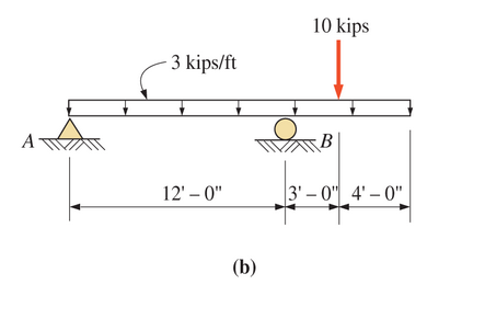
Refer to the indicated problem and draw complete shear and bending moment diagrams. Show ordinates at key points and indicate magnitude of shear and moment.
Neglect the beam weight.13.57 Problem 13.10 (b)
Expert Solution & Answer
Want to see the full answer?
Check out a sample textbook solution
Students have asked these similar questions
Hi can you please help me with the attached question?
I need the proofs for this equation and derivation of the equation include all graphs needed
Please can you help me with the attached question?
Chapter 13 Solutions
Applied Statics and Strength of Materials (6th Edition)
Ch. 13 - through 13.6 Calculate the reactions at points A...Ch. 13 - Calculate the reactions at points A and B for the...Ch. 13 - through 13.6 Calculate the reactions at points A...Ch. 13 - Calculate the reactions at points A and B for the...Ch. 13 - Calculate the reactions at points A and B for the...Ch. 13 - Calculate the reactions at points A and B for the...Ch. 13 - Calculate the shear and bending moment at 4 m and...Ch. 13 - Calculate the shear and bending moment at 3 ft and...Ch. 13 - Calculate the shear and bending moment at midspan...Ch. 13 - Calculate the shear and bending moment at 5 ft and...
Ch. 13 - Calculate the shear and bending moment at 5 m and...Ch. 13 - For the beams shown, draw complete shear diagrams.Ch. 13 - For the beams shown, draw complete shear diagrams.Ch. 13 - Prob. 13.14PCh. 13 - For the beams shown, draw complete shear diagrams.Ch. 13 - For the beams shown (next page), draw complete...Ch. 13 - For the beams shown (next page), draw complete...Ch. 13 - For the beams shown (next page), draw complete...Ch. 13 - For the beams shown (next page), draw complete...Ch. 13 - For the beams shown (next page), draw complete...Ch. 13 - For the beams shown, draw complete shear and...Ch. 13 - For the beams shown, draw complete shear and...Ch. 13 - For the beams shown, draw complete shear and...Ch. 13 - A moving-load system is composed of two...Ch. 13 - A moving-load system is composed of two...Ch. 13 - One of the standard truck loads used in the design...Ch. 13 - Write a computer program that will calculate the...Ch. 13 - Write a program that will calculate the shear and...Ch. 13 - Viking Consultants wishes to generate a table of...Ch. 13 - Calculate the reactions for the simple beams...Ch. 13 - Calculate the reactions for the overhanging beams...Ch. 13 - Calculate the reactions at points A and B for the...Ch. 13 - Calculate the reactions at points A and B for the...Ch. 13 - For the beams of Problem 13.33, calculate the...Ch. 13 - For the beam shown, calculate the shear and...Ch. 13 - Calculate the shear and bending moment at points 4...Ch. 13 - Calculate the shear arid bending moment at points...Ch. 13 - Calculate the shear and bending moment at points...Ch. 13 - Refer to the beam shown and draw complete shear...Ch. 13 - Refer to the beam shown and draw complete shear...Ch. 13 - Refer to the beam shown and draw complete shear...Ch. 13 - Refer to the beam shown and draw complete shear...Ch. 13 - Refer to the beam shown and draw complete shear...Ch. 13 - Refer to the beam shown and draw complete shear...Ch. 13 - Refer to the beam shown and draw complete shear...Ch. 13 - Refer to the beam shown and draw complete shear...Ch. 13 - Refer to the beam shown and draw complete shear...Ch. 13 - Refer to the indicated problem and draw complete...Ch. 13 - Refer to the indicated problem and draw complete...Ch. 13 - Refer to the indicated problem and draw complete...Ch. 13 - Refer to the indicated problem and draw complete...Ch. 13 - Refer to the indicated problem and draw complete...Ch. 13 - Refer to the indicated problem and draw complete...Ch. 13 - Refer to the indicated problem and draw complete...Ch. 13 - Refer to the indicated problem and draw complete...Ch. 13 - Refer to the indicated problem and draw complete...Ch. 13 - Refer to the indicated problem and draw complete...Ch. 13 - Refer to the indicated problem and draw complete...Ch. 13 - A two-axle roller with axles 5 m apart passes over...Ch. 13 - A moving load system with wheels at fixed...Ch. 13 - A moving-load system with wheels spaced as shown...
Knowledge Booster


Learn more about
Need a deep-dive on the concept behind this application? Look no further. Learn more about this topic, mechanical-engineering and related others by exploring similar questions and additional content below.Similar questions
- Please can you help me with the attached question?arrow_forward4. The rod ABCD is made of an aluminum for which E = 70 GPa. For the loading shown, determine the deflection of (a) point B, (b) point D. 1.75 m Area = 800 mm² 100 kN B 1.25 m с Area = 500 mm² 75 kN 1.5 m D 50 kNarrow_forwardResearch and select different values for the R ratio from various engine models, then analyze how these changes affect instantaneous velocity and acceleration, presenting your findings visually using graphs.arrow_forward
- Qu. 7 The v -t graph of a car while travelling along a road is shown. Draw the s -t and a -t graphs for the motion. I need to draw a graph and I need to show all work step by step please do not get short cut from dtnaarrow_forwardAn unpressurized cylindrical tank with a 100-foot diameter holds a 40-foot column of water. What is total force acting against the bottom of the tank?arrow_forward7. In the following problems check to see if the set S is a vector subspace of the corresponding R. If it is not, explain why not. If it is, then find a basis and the dimension. (a) S = (b) S = {[],+,"} X1 x12x2 = x3 CR³ {[1], 4+4 = 1} CR³ X2arrow_forward
- AAA Show laplace transform on 1; (+) to L (y(+)) : SY(s) = x (0) Y(s) = £ [lx (+)] = 5 x(+) · est de 2 -St L [ y (^) ] = So KG) et de D 2 D D AA Y(A) → Y(s) Ŷ (+) → s Y(s) -yarrow_forward1) In each of the following scenarios, based on the plane of impact (shown with an (n, t)) and the motion of mass 1, draw the direction of motion of mass 2 after the impact. Note that in all scenarios, mass 2 is initially at rest. What can you say about the nature of the motion of mass 2 regardless of the scenario? m1 15 <+ m2 2) y "L χ m1 m2 m1 בז m2 Farrow_forward8. In the following check to see if the set S is a vector subspace of the corresponding Rn. If it is not, explain why not. If it is, then find a basis and the dimension. X1 (a) S = X2 {[2], n ≤ n } c X1 X2 CR² X1 (b) S X2 = X3 X4 x1 + x2 x3 = 0arrow_forward
arrow_back_ios
SEE MORE QUESTIONS
arrow_forward_ios
Recommended textbooks for you
 International Edition---engineering Mechanics: St...Mechanical EngineeringISBN:9781305501607Author:Andrew Pytel And Jaan KiusalaasPublisher:CENGAGE L
International Edition---engineering Mechanics: St...
Mechanical Engineering
ISBN:9781305501607
Author:Andrew Pytel And Jaan Kiusalaas
Publisher:CENGAGE L
Understanding Shear Force and Bending Moment Diagrams; Author: The Efficient Engineer;https://www.youtube.com/watch?v=C-FEVzI8oe8;License: Standard YouTube License, CC-BY
Bending Stress; Author: moodlemech;https://www.youtube.com/watch?v=9QIqewkE6xM;License: Standard Youtube License