
Fundamentals of Electric Circuits
6th Edition
ISBN: 9780078028229
Author: Charles K Alexander, Matthew Sadiku
Publisher: McGraw-Hill Education
expand_more
expand_more
format_list_bulleted
Concept explainers
Videos
Textbook Question
thumb_up100%
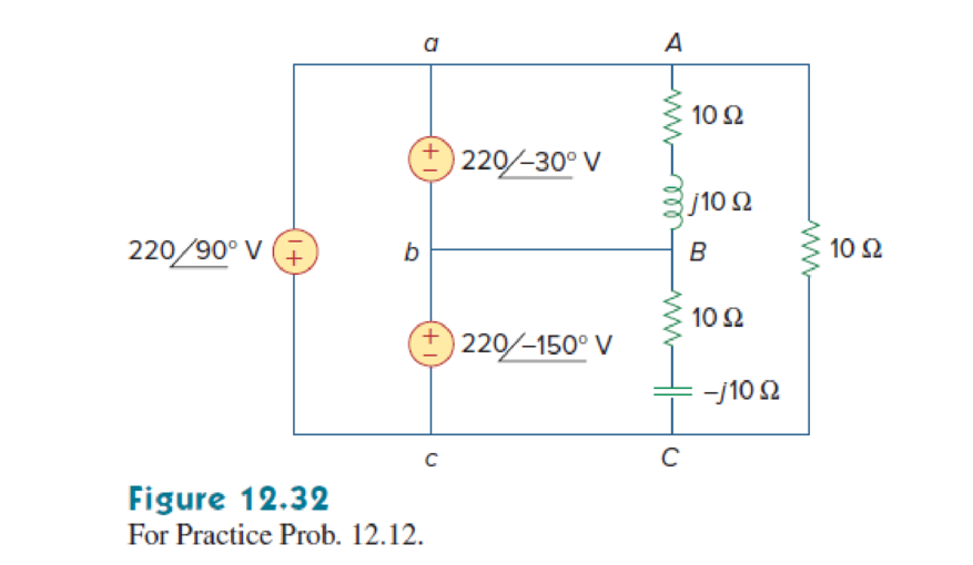
Chapter 12.9, Problem 12PP
For the unbalanced circuit in Fig. 12.32, use PSpice to find the generator current Ica, the line current IcC, and the phase current IAB.
Expert Solution & Answer
Want to see the full answer?
Check out a sample textbook solution
Students have asked these similar questions
80 V
300 Ω
t = 0
500 i(t)
Vc(t)
40 nF
2,5 mH
-
Problem 1: Two-Force Equilibrium
A 12 kg traffic light is suspended by two cables
attached to a ceiling. Determine the force in Cable 1
(AB) and Cable 2 (AC). In other words, determine the
tension in each cable, assuming the system is in static
equilibrium.
B
If the Z-axis changes, what is the effect
A circularly polarized wave, traveling in the +z-direction, is received by an elliptically
polarized antenna whose reception characteristics near the main lobe are given approx-
imately by
E₁ = (2â, + jâ] f(r. 8. d)
Find the polarization loss factor PLF (dimensionless and in dB) when the incident wave
is
(a) right-hand (CW)
(b) left-hand (CCW)
An elliptically polarized wave traveling in the negative z-direction is received by a circularly polarized
antenna. The vector describing the polarization of the incident wave is given by Ei= 2ax + jay .Find the
polarization loss factor PLF (dimensionless and in dB) when the wave that would be transmitted by the
antenna is (a) right-hand CP (b) left-hand CP.
Chapter 12 Solutions
Fundamentals of Electric Circuits
Ch. 12.2 - Given that Vbn=22030V, find Van and Vcn, assuming...Ch. 12.3 - A Y-connected balanced three-phase generator with...Ch. 12.4 - One line voltage of a balanced Y-connected source...Ch. 12.5 - A positive-sequence, balanced -connected source...Ch. 12.6 - In a balanced -Y circuit, Vab=44015 and ZY = (12 +...Ch. 12.7 - For the Y-Y circuit in Practice Prob. 12.2,...Ch. 12.7 - Calculate the line current required for a 30-kW...Ch. 12.7 - Assume that the two balanced loads in Fig....Ch. 12.8 - The unbalanced -load of Fig. 12.24 is supplied by...Ch. 12.8 - Find the line currents in the unbalanced...
Ch. 12.9 - Prob. 11PPCh. 12.9 - For the unbalanced circuit in Fig. 12.32, use...Ch. 12.10 - Repeat Example 12.13 for the network in Fig. 12.24...Ch. 12.10 - Let the line voltage VL = 208 V and the wattmeter...Ch. 12.10 - If the load in Fig. 12.35 is delta-connected with...Ch. 12 - What is the phase sequence of a three-phase motor...Ch. 12 - If in an acb phase sequence, , then Vcn is:Ch. 12 - Which of these is not a required condition for a...Ch. 12 - Prob. 4RQCh. 12 - Prob. 5RQCh. 12 - In a Y-Y system, a line voltage of 220 V produces...Ch. 12 - In a - system, a phase voltage of 100 V produces a...Ch. 12 - When a Y-connected load is supplied by voltages in...Ch. 12 - Prob. 9RQCh. 12 - Prob. 10RQCh. 12 - If Vab = 400 V in a balanced Y-connected...Ch. 12 - What is the phase sequence of a balanced...Ch. 12 - Given a balanced Y-connected three-phase generator...Ch. 12 - A three-phase system with abc sequence and VL =...Ch. 12 - For a Y-connected load, the time-domain...Ch. 12 - Using Fig. 12.41, design a problem to help other...Ch. 12 - Obtain the line currents in the three-phase...Ch. 12 - In a balanced three-phase Y-Y system, the source...Ch. 12 - A balanced Y-Y four-wire system has phase voltages...Ch. 12 - For the circuit in Fig. 12.43, determine the...Ch. 12 - In the Y- system shown in Fig. 12.44, the source...Ch. 12 - Using Fig. 12.45, design a problem to help other...Ch. 12 - In the balanced three-phase Y- system in Fig....Ch. 12 - Obtain the line currents in the three-phase...Ch. 12 - The circuit in Fig. 12.48 is excited by a balanced...Ch. 12 - A balanced delta-connected load has a phase...Ch. 12 - A positive sequence wye-connected source where ,...Ch. 12 - If Van = 22060 V in the network of Fig. 12.49,...Ch. 12 - For the - circuit of Fig. 12.50, calculate the...Ch. 12 - Prob. 20PCh. 12 - Three 440-V generators form a delta-connected...Ch. 12 - Find the line currents IaA, IbB, and IcC in the...Ch. 12 - A balanced delta connected source is connected to...Ch. 12 - A balanced delta-connected source has phase...Ch. 12 - In the circuit of Fig. 12.54, if , , , find the...Ch. 12 - Using Fig. 12.55, design a problem to help other...Ch. 12 - A -connected source supplies power to a...Ch. 12 - The line-to-line voltages in a Y-load have a...Ch. 12 - A balanced three-phase Y- system has V rms and Z =...Ch. 12 - In Fig. 12.56, the rms value of the line voltage...Ch. 12 - A balanced delta-connected load is supplied by a...Ch. 12 - Design a problem to help other students better...Ch. 12 - A three-phase source delivers 4.8 kVA to a...Ch. 12 - A balanced wye-connected load with a phase...Ch. 12 - Three equal impedances, 60 + j30 each, are...Ch. 12 - A 4200-V, three-phase transmission line has an...Ch. 12 - The total power measured in a three-phase system...Ch. 12 - Given the circuit in Fig. 12.57 below, find the...Ch. 12 - Find the real power absorbed by the load in Fig....Ch. 12 - For the three-phase circuit in Fig. 12.59, find...Ch. 12 - A balanced delta-connected load draws 5 kW at a...Ch. 12 - A balanced three-phase generator delivers 7.2 kW...Ch. 12 - Refer to Fig. 12.48. Obtain the complex power...Ch. 12 - A three-phase line has an impedance of 1 + j3 per...Ch. 12 - A balanced wye-connected load is connected to the...Ch. 12 - A three-phase load consists of three 100-...Ch. 12 - The following three parallel-connected three-phase...Ch. 12 - A balanced, positive-sequence wye-connected source...Ch. 12 - Each phase load consists of a 20- resistor and a...Ch. 12 - A balanced three-phase source with VL = 240 V rms...Ch. 12 - Consider the wye-delta system shown in Fig. 12.60....Ch. 12 - A four-wire wye-wye circuit has...Ch. 12 - Using Fig. 12.61, design a problem that will help...Ch. 12 - A balanced three-phase Y-source with VP = 880 V...Ch. 12 - A three-phase supply, with the line-to-line...Ch. 12 - Using Fig. 12.63, design a problem to help other...Ch. 12 - Determine the line currents for the three-phase...Ch. 12 - Solve Prob. 12.10 using PSpice or MultiSim. For...Ch. 12 - The source in Fig. 12.65 is balanced and exhibits...Ch. 12 - Use PSpice or MultiSim to determine Io in the...Ch. 12 - Given the circuit in Fig. 12.67, use PSpice or...Ch. 12 - Using Fig. 12.68, design a problem to help other...Ch. 12 - Use PSpice or MultiSim to find currents IaA and...Ch. 12 - For the circuit in Fig. 12.58, use PSpice or...Ch. 12 - A balanced three-phase circuit is shown in Fig....Ch. 12 - A three-phase, four-wire system operating with a...Ch. 12 - As shown in Fig. 12.72, a three-phase four-wire...Ch. 12 - Meter readings for a three-phase wye-connected...Ch. 12 - A certain store contains three balanced...Ch. 12 - The two-wattmeter method gives P1=1200W and...Ch. 12 - In Fig. 12.73, two wattmeters are properly...Ch. 12 - If wattmeters W1 and W2 are properly connected...Ch. 12 - For the circuit displayed in Fig. 12.74, find the...Ch. 12 - Predict the wattmeter readings for the circuit in...Ch. 12 - Prob. 75PCh. 12 - Show that the I2R losses will be higher for a...Ch. 12 - A three-phase generator supplied 10 kVA at a power...Ch. 12 - Prob. 78CPCh. 12 - A balanced three-phase generator has an abc phase...Ch. 12 - A balanced three-phase source furnishes power to...Ch. 12 - A professional center is supplied by a balanced...Ch. 12 - A balanced three-phase system has a distribution...Ch. 12 - A commercially available three-phase inductive...Ch. 12 - Figure 12.76 displays a three-phase...Ch. 12 - Design a three-phase heater with suitable...Ch. 12 - For the single-phase three-wire system in Fig....Ch. 12 - Consider the single-phase three-wire system shown...
Knowledge Booster


Learn more about
Need a deep-dive on the concept behind this application? Look no further. Learn more about this topic, electrical-engineering and related others by exploring similar questions and additional content below.Similar questions
- Medium 1 is a lossless dielectric (ε₁=ε,ε, μ₁=μ₁, σ₁=0) Medium 2 is a lossless dielectric (ε=&&₂, μ=μ₁, σ₁=0) [бг Мо о = = 0] [2 Mo σ₂ = 0] E₁ (z) = Ele² + Пe+jB₁²] E2 (z) = E Te² and tot = constant 1. For the case εr1 = 1, &r2= 16, E₁x=1 V/m and a frequency f = 750 MHz determine: λι = n₁ = 22 = n2= r = T= 2. The magnitude |E1 tot (z)| will show an interference pattern in region 1 as: E˜(z)=E,{1+Te®®]e¯MS =E||{1+Te^^^^\]e=##} | = |E|+Texp(j) For an incident field E₁x=1 V/m SKETCH the magnitude of E1 tot (z)| and |E20 (z) on the graph below. Plot the values at 2/4 increments and sketch between. What is the SWR?arrow_forwardPlease don't use AIarrow_forwardPlease don't use AIarrow_forward
- 3) In the ideal autotransformer circuit shown below find 11, 12 and lo. Find the average power delivered to the load. (hint: write KVL for both sides) 20/30° V(+ 2-1602 200 turns V₂ 10 + j40 Ω 80 turns V₁arrow_forward11-2) Now consider that white noise (i.e., noise with a PSD that is constant with frequency) is introduced in the channel of the system described in the previous problem. An ideal low pass filter is used at the receiver input to reduce the noise as much as possible, while transmitting the desired signal. (a) By what factor should the cutoff frequency of the noise reduction filter be reduced in the 16-PAM case, compared to binary? (b) By what factor will the noise power at the decision circuit be reduced in the 16-PAM case? (c) By what factor will the noise amplitude at the decision circuit be reduced in the 16-PAM case? (d) To obtain the same symbol error rate for 16-PAM as for binary, how should the minimum level spacing for 16-PAM compare to binary? (e) If the 16-PAM level spacing is adjusted according to part (d) above, by what factor will the average signal power be increased in the 16-PAM case, compared to binary?arrow_forward11-1) similar to Lathi & Ding, Prob. P.6.7-5 Data at a bit rate Rb must be transmitted using either binary NRZ polar signaling or 16-ary PAM NRZ polar signaling. (a) By what factor will the symbol rate be reduced in the 16-PAM case? (b) By what factor will bandwidth required from the (lowpass) channel be reduced in the 16-PAM case? (c) Assuming the minimum spacing between pulse levels must be the same in both cases, by what factor will the average power be increased in the 16-PAM case? [Hint: take the pulse amplitudes to be ±A in the binary case, and ±A, ±3A, ±5A,..., ±154, and recall that scaling pulse amplitude by a factor k scales the pulse energy by a factor R². Assume that the data is random, so that all 16 levels are equally likely, and that the same pulse shape is used in both cases.] Warning: Solutions to the textbook problem that are posted online are mostly wrong. Work it out for yourself.arrow_forward
- 11-3) similar to Lathi & Ding, Prob. P.6.8-1 Consider the carrier modulator shown in the figure below, which transmits a binary carrier signal. The baseband generator uses polar NRZ signaling with rectangular pulses. The data rate is 8 Mbit/s. (a) If the modulator generates a binary PSK signal, what is the bandwidth of the modulated output? (b) If the modulator generates FSK with the difference fel - fco = 6 MHz (cf. Fig 6.32c), determine the modulated signal bandwidth. Binary data source Baseband signal generator Modulated output Modulator N-E---arrow_forwardFor the circuit shown, find (i) closed-loop voltage gain (ii) Z i of the circuit (iii) f_max. The slew rate is 0.6V/us. ((write your answer in Kilo ohm)) 2Vpp R ww 20 kQ R₁ ww 200 ΚΩ 9+18 V - 18 V 10 kn R₁₂ ΚΩ ((write your answer in KHz))arrow_forwardillustrate the phenomenon of phase reversal in CE amplifier i- When signal current =OA, so IB-8uA ii- When input signal reaches positive peak, so IB=16uA ii- When input signal reaches negative peak, so IB=4uA R₁ www + Vcc = 12V Rc=6kn 16 A 8 μA 4 μА 0 www RE ẞ = 100 VCarrow_forward
- In the circuit shown, find the voltage gain. Given that ẞ = 80 and input resistance Rin=2kQ. SIGNAL +10 V Rc=6kn 4-2 210arrow_forwardFor the transistor amplifier shown, R₁-11kQ, R2=6kQ, Rc=2kQ, RE-3kQ and R₁=2k0. (i) Draw d.c. load line (ii) Determine the DC operating point (iii) Draw a.c. load line. Assume V_BE = 0.7 V. and determine the new operating point + Vcc = 15 V RC Cc Cin R1 wwwwww wwwww R₁₂ RE CE RLarrow_forwardthe first part is the second part write your answer such as: (AND, OR, INVERTER, NAND, NOR) D₁ AK D, R₁ B K First Part? the third part is , and the total are R4 R7 Output R5 R₁ T R6 R3 -UBB Second Part? Third Part? Total?arrow_forward
arrow_back_ios
SEE MORE QUESTIONS
arrow_forward_ios
Recommended textbooks for you
 Power System Analysis and Design (MindTap Course ...Electrical EngineeringISBN:9781305632134Author:J. Duncan Glover, Thomas Overbye, Mulukutla S. SarmaPublisher:Cengage Learning
Power System Analysis and Design (MindTap Course ...
Electrical Engineering
ISBN:9781305632134
Author:J. Duncan Glover, Thomas Overbye, Mulukutla S. Sarma
Publisher:Cengage Learning
What is the Difference Between Single Phase and Three Phase???; Author: Electrician U;https://www.youtube.com/watch?v=FEydcr4wJw0;License: Standard Youtube License