
Fundamentals of Electric Circuits
6th Edition
ISBN: 9780078028229
Author: Charles K Alexander, Matthew Sadiku
Publisher: McGraw-Hill Education
expand_more
expand_more
format_list_bulleted
Concept explainers
Videos
Textbook Question
Chapter 12, Problem 2RQ
If in an acb phase sequence, 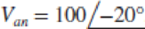 , then Vcn is:


Expert Solution & Answer
Want to see the full answer?
Check out a sample textbook solution
Students have asked these similar questions
5.
Three single-phase transformers rated at 250 kVA, 7200 V/600 V, 60 Hz, are
connected in wye-delta on a 12470 V, 3-phase line. If the load is 450 kVA, calculate the following
currents:
(1) In the incoming and outgoing transmission lines
(2) In the primary and secondary windings
(3) If this transformer is used to raise the voltage of a 3-phase, 600 V line to 7.2 kV. (a) How
must they be connected? (b) Calculate the line currents for a 600 kVA load. (c) Calculate the
corresponding primary and secondary currents.
please answer handwritten not chatgbt
please answer handwritten not chatgbt
Chapter 12 Solutions
Fundamentals of Electric Circuits
Ch. 12.2 - Given that Vbn=22030V, find Van and Vcn, assuming...Ch. 12.3 - A Y-connected balanced three-phase generator with...Ch. 12.4 - One line voltage of a balanced Y-connected source...Ch. 12.5 - A positive-sequence, balanced -connected source...Ch. 12.6 - In a balanced -Y circuit, Vab=44015 and ZY = (12 +...Ch. 12.7 - For the Y-Y circuit in Practice Prob. 12.2,...Ch. 12.7 - Calculate the line current required for a 30-kW...Ch. 12.7 - Assume that the two balanced loads in Fig....Ch. 12.8 - The unbalanced -load of Fig. 12.24 is supplied by...Ch. 12.8 - Find the line currents in the unbalanced...
Ch. 12.9 - Prob. 11PPCh. 12.9 - For the unbalanced circuit in Fig. 12.32, use...Ch. 12.10 - Repeat Example 12.13 for the network in Fig. 12.24...Ch. 12.10 - Let the line voltage VL = 208 V and the wattmeter...Ch. 12.10 - If the load in Fig. 12.35 is delta-connected with...Ch. 12 - What is the phase sequence of a three-phase motor...Ch. 12 - If in an acb phase sequence, , then Vcn is:Ch. 12 - Which of these is not a required condition for a...Ch. 12 - Prob. 4RQCh. 12 - Prob. 5RQCh. 12 - In a Y-Y system, a line voltage of 220 V produces...Ch. 12 - In a - system, a phase voltage of 100 V produces a...Ch. 12 - When a Y-connected load is supplied by voltages in...Ch. 12 - Prob. 9RQCh. 12 - Prob. 10RQCh. 12 - If Vab = 400 V in a balanced Y-connected...Ch. 12 - What is the phase sequence of a balanced...Ch. 12 - Given a balanced Y-connected three-phase generator...Ch. 12 - A three-phase system with abc sequence and VL =...Ch. 12 - For a Y-connected load, the time-domain...Ch. 12 - Using Fig. 12.41, design a problem to help other...Ch. 12 - Obtain the line currents in the three-phase...Ch. 12 - In a balanced three-phase Y-Y system, the source...Ch. 12 - A balanced Y-Y four-wire system has phase voltages...Ch. 12 - For the circuit in Fig. 12.43, determine the...Ch. 12 - In the Y- system shown in Fig. 12.44, the source...Ch. 12 - Using Fig. 12.45, design a problem to help other...Ch. 12 - In the balanced three-phase Y- system in Fig....Ch. 12 - Obtain the line currents in the three-phase...Ch. 12 - The circuit in Fig. 12.48 is excited by a balanced...Ch. 12 - A balanced delta-connected load has a phase...Ch. 12 - A positive sequence wye-connected source where ,...Ch. 12 - If Van = 22060 V in the network of Fig. 12.49,...Ch. 12 - For the - circuit of Fig. 12.50, calculate the...Ch. 12 - Prob. 20PCh. 12 - Three 440-V generators form a delta-connected...Ch. 12 - Find the line currents IaA, IbB, and IcC in the...Ch. 12 - A balanced delta connected source is connected to...Ch. 12 - A balanced delta-connected source has phase...Ch. 12 - In the circuit of Fig. 12.54, if , , , find the...Ch. 12 - Using Fig. 12.55, design a problem to help other...Ch. 12 - A -connected source supplies power to a...Ch. 12 - The line-to-line voltages in a Y-load have a...Ch. 12 - A balanced three-phase Y- system has V rms and Z =...Ch. 12 - In Fig. 12.56, the rms value of the line voltage...Ch. 12 - A balanced delta-connected load is supplied by a...Ch. 12 - Design a problem to help other students better...Ch. 12 - A three-phase source delivers 4.8 kVA to a...Ch. 12 - A balanced wye-connected load with a phase...Ch. 12 - Three equal impedances, 60 + j30 each, are...Ch. 12 - A 4200-V, three-phase transmission line has an...Ch. 12 - The total power measured in a three-phase system...Ch. 12 - Given the circuit in Fig. 12.57 below, find the...Ch. 12 - Find the real power absorbed by the load in Fig....Ch. 12 - For the three-phase circuit in Fig. 12.59, find...Ch. 12 - A balanced delta-connected load draws 5 kW at a...Ch. 12 - A balanced three-phase generator delivers 7.2 kW...Ch. 12 - Refer to Fig. 12.48. Obtain the complex power...Ch. 12 - A three-phase line has an impedance of 1 + j3 per...Ch. 12 - A balanced wye-connected load is connected to the...Ch. 12 - A three-phase load consists of three 100-...Ch. 12 - The following three parallel-connected three-phase...Ch. 12 - A balanced, positive-sequence wye-connected source...Ch. 12 - Each phase load consists of a 20- resistor and a...Ch. 12 - A balanced three-phase source with VL = 240 V rms...Ch. 12 - Consider the wye-delta system shown in Fig. 12.60....Ch. 12 - A four-wire wye-wye circuit has...Ch. 12 - Using Fig. 12.61, design a problem that will help...Ch. 12 - A balanced three-phase Y-source with VP = 880 V...Ch. 12 - A three-phase supply, with the line-to-line...Ch. 12 - Using Fig. 12.63, design a problem to help other...Ch. 12 - Determine the line currents for the three-phase...Ch. 12 - Solve Prob. 12.10 using PSpice or MultiSim. For...Ch. 12 - The source in Fig. 12.65 is balanced and exhibits...Ch. 12 - Use PSpice or MultiSim to determine Io in the...Ch. 12 - Given the circuit in Fig. 12.67, use PSpice or...Ch. 12 - Using Fig. 12.68, design a problem to help other...Ch. 12 - Use PSpice or MultiSim to find currents IaA and...Ch. 12 - For the circuit in Fig. 12.58, use PSpice or...Ch. 12 - A balanced three-phase circuit is shown in Fig....Ch. 12 - A three-phase, four-wire system operating with a...Ch. 12 - As shown in Fig. 12.72, a three-phase four-wire...Ch. 12 - Meter readings for a three-phase wye-connected...Ch. 12 - A certain store contains three balanced...Ch. 12 - The two-wattmeter method gives P1=1200W and...Ch. 12 - In Fig. 12.73, two wattmeters are properly...Ch. 12 - If wattmeters W1 and W2 are properly connected...Ch. 12 - For the circuit displayed in Fig. 12.74, find the...Ch. 12 - Predict the wattmeter readings for the circuit in...Ch. 12 - Prob. 75PCh. 12 - Show that the I2R losses will be higher for a...Ch. 12 - A three-phase generator supplied 10 kVA at a power...Ch. 12 - Prob. 78CPCh. 12 - A balanced three-phase generator has an abc phase...Ch. 12 - A balanced three-phase source furnishes power to...Ch. 12 - A professional center is supplied by a balanced...Ch. 12 - A balanced three-phase system has a distribution...Ch. 12 - A commercially available three-phase inductive...Ch. 12 - Figure 12.76 displays a three-phase...Ch. 12 - Design a three-phase heater with suitable...Ch. 12 - For the single-phase three-wire system in Fig....Ch. 12 - Consider the single-phase three-wire system shown...
Knowledge Booster


Learn more about
Need a deep-dive on the concept behind this application? Look no further. Learn more about this topic, electrical-engineering and related others by exploring similar questions and additional content below.Similar questions
- Don't use ai to answer I will report you answerarrow_forwardThe values of the elements in the circuit given in the figure are given below. Find the maximum average power that can be transferred to the ZL load. Vg=5cos(10000t) VoltR=38 kilo ohmC=35 nano faradL=150 milli henryarrow_forwardPrelab Information 1. Laboratory Preliminary Discussion Second-order RC Circuit Analysis The second-order RC circuit shown in figure 1 below represents all voltages and impedances as functions of the complex variable, s. Note, of course, that the impedances associated with Rs, R₁, and R2 are constant independent of frequency, so the 's' notation is omitted. Again, one of the advantages of s-domain analysis is that we can apply all of the circuit analysis techniques learned for AC and DC circuits. To generate the s-domain expression for the output voltage, Vout(s) = Vc2(s), for the circuit shown in figure 1, we can apply voltage division in the s-domain as shown in equation 1 below. Equation 1 will be used in the prelab computations to find an expression for the output voltage, vc2(t), in the time domain. Note also that when we collect frequency response data for the circuit it will be operating at AC steady-state conditions for each frequency tested. Note that under AC steady-state…arrow_forward
- Don't use ai to answer I will report you answerarrow_forwardThe power values of the loads in the circuit given in the figure are given below. Accordingly, which of the following is the RMS value of the Vs voltage amplitude? Load 1 (L1): the power factor is 1 and draws 13 kW of power,Load 2 (L2): draws 1 kVA at a forward power factor of 0.6,Load 3 (L3): draws 4 kW of average power and gives 3 kVAR of reactive power.arrow_forwardThe values of the elements in the circuit given in the figure are given below. Find the average power value on the R2 resistor. (Hint: First find the current of the R2 resistor with the loop current method. Four mutual inductance effect expressions should be added to each of the two loop equations.) Vs=238 voltsR1=13 ohmsR2=15 ohmsarrow_forward
- Don't use ai to answer I will report you answerarrow_forwardA transformer bank is composed of three single-phase transformers of10kVA, 20kV/200V; copper losses are 100 W and core lossesthey are 50 W. The bank is connected in Delta on the high voltage side and in star on the sidethe low-voltage side. A. What are the values of voltages B.What are the values of currents C. losses in the core and losses in copper. D. nominal power of the transformer bank.Solve by one of the experts, not using artificial intelligencearrow_forwardA 50 kVA, 13800/208 V transformer connected in Dy has an Rcc of 1% and aXcc of 7% per unit. A. What is the voltage regulation at full load and fp 0.8 in delay using the values of theimpedance (Ω).b. What is the voltage regulation under the same conditions using the system per unit Solve by one of the experts, not using artificial inteliggencearrow_forward
arrow_back_ios
SEE MORE QUESTIONS
arrow_forward_ios
Recommended textbooks for you
 Power System Analysis and Design (MindTap Course ...Electrical EngineeringISBN:9781305632134Author:J. Duncan Glover, Thomas Overbye, Mulukutla S. SarmaPublisher:Cengage Learning
Power System Analysis and Design (MindTap Course ...
Electrical Engineering
ISBN:9781305632134
Author:J. Duncan Glover, Thomas Overbye, Mulukutla S. Sarma
Publisher:Cengage Learning
Fault Analysis in Power Systems part 1a; Author: GeneralPAC: Power System Tutorials;https://www.youtube.com/watch?v=g8itg4MOjok;License: Standard youtube license