
Mechanics of Materials (10th Edition)
10th Edition
ISBN: 9780134319650
Author: Russell C. Hibbeler
Publisher: PEARSON
expand_more
expand_more
format_list_bulleted
Concept explainers
Videos
Textbook Question
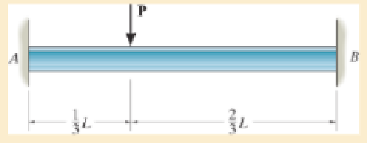
Chapter 12.7, Problem 12.99P
Determine the reactions at the supports A and B, then draw the shear and moment diagram. El is constant. Neglect the effect of axial load.
Expert Solution & Answer

Learn your wayIncludes step-by-step video

schedule18:16
Students have asked these similar questions
The cardiovascular countercurrent heat exchnager mechanism is to warm venous blood from 28 degrees C to 35 degrees C at a mass flow rate of 2 g/s. The artery inflow temp is 37 degrees C at a mass flow rate of 5 g/s. The average diameter of the vein is 5 cm and the overall heat transfer coefficient is 125 W/m^2*K. Determine the overall blood vessel length needed too warm the venous blood to 35 degrees C if the specific heat of both arterial and venous blood is constant and equal to 3475 J/kg*K.
The forces Qy=12 kNQy=12kN and Qz=16 kNQz=16kN act on the profile at the shear center C. Calculate:
a) Shear flow at point B (2 points)b) Shear stress at point D (3 points)
Consider the feedback controlled blending system shown below, which is designed to keep theoutlet concentration constant despite potential variations in the stream 1 composition. The density of all streamsis 920 kg/m3. At the nominal steady state, the flow rates of streams 1 and 2 are 950 and 425 kg/min,respectively, the liquid level in the tank is 1.3 m, the incoming mass fractions are x1 = 0.27, x2 = 0.54. Noticethe overflow line, indicating that the liquid level remains constant (i.e. any change in total inlet flow ratetranslates immediately to the same change in the outlet flow rate). You may assume the stream 1 flowrate andthe stream 2 composition are both constant. Use minutes as the time unit throughout this problem.
d) Derive the first order process and disturbance transfer functions;Gp= Kp/(tou*s+1) and Gd=Kd/(tou*s+1) and calculate and list the values and units of the parameters.
e) Using the given information, write the general forms of Gm, GIP, and Gv below(in terms of…
Chapter 12 Solutions
Mechanics of Materials (10th Edition)
Ch. 12.2 - In each case, determine the internal bending...Ch. 12.2 - Determine the slope and deflection of end A of the...Ch. 12.2 - Determine the slope and deflection of end A of the...Ch. 12.2 - Determine the slope of end A of the cantilevered...Ch. 12.2 - Determine the maximum deflection of the simply...Ch. 12.2 - Determine the maximum deflection of the simply...Ch. 12.2 - Determine the slope of the simply supported beam...Ch. 12.2 - An L2 steel strap having a thickness of 0.125 in....Ch. 12.2 - The L2 steel blade of the band saw wraps around...Ch. 12.2 - A picture is taken of a man performing a pole...
Ch. 12.2 - El is constant. Prob. 124Ch. 12.2 - Determine the deflection of end C of the...Ch. 12.2 - Determine the elastic curve for the cantilevered...Ch. 12.2 - The A-36 steel beam has a depth of 10 in. and is...Ch. 12.2 - Determine the equations of the elastic curve using...Ch. 12.2 - Determine the equations of the elastic curve for...Ch. 12.2 - Determine the equations of the elastic curve using...Ch. 12.2 - Determine the equations of the elastic curve using...Ch. 12.2 - Draw the bending-moment diagram for the shaft and...Ch. 12.2 - Determine the maximum deflection of the beam and...Ch. 12.2 - The simply supported shaft has a moment of inertia...Ch. 12.2 - A torque wrench is used to tighten the nut on a...Ch. 12.2 - The pipe can be assumed roller supported at its...Ch. 12.2 - Determine the equations of the elastic curve for...Ch. 12.2 - The bar is supported by a roller constraint at B,...Ch. 12.2 - Determine the deflection at B of the bar in Prob....Ch. 12.2 - Determine the equations of the elastic curve using...Ch. 12.2 - Determine the maximum deflection of the solid...Ch. 12.2 - Determine the elastic curve for the cantilevered...Ch. 12.2 - Determine the equations of the elastic curve using...Ch. 12.2 - Determine the equations of the elastic curve using...Ch. 12.2 - The floor beam of the airplane is subjected to the...Ch. 12.2 - Determine the maximum deflection of the simply...Ch. 12.2 - The beam is made of a material having a specific...Ch. 12.2 - Determine the slope at end B and the maximum...Ch. 12.2 - Determine the equation of the elastic curve using...Ch. 12.2 - Determine the equations of the elastic curve using...Ch. 12.3 - The shaft is supported at A by a journal bearing...Ch. 12.3 - The shaft supports the two pulley loads shown....Ch. 12.3 - The beam is made of a ceramic material. If it is...Ch. 12.3 - Determine the equation of the elastic curve, the...Ch. 12.3 - The beam is subjected to the load shown. Determine...Ch. 12.3 - Determine the equation of the elastic curve, the...Ch. 12.3 - Determine the equation of the elastic curve and...Ch. 12.3 - The shaft supports the two pulley loads. Determine...Ch. 12.3 - Determine the maximum deflection of the...Ch. 12.3 - Determine the slope at A and the deflection of end...Ch. 12.3 - Determine the maximum deflection in region AB of...Ch. 12.3 - Prob. 12.42PCh. 12.3 - Prob. 12.43PCh. 12.3 - Prob. 12.44PCh. 12.3 - Prob. 12.45PCh. 12.3 - Prob. 12.46PCh. 12.3 - Prob. 12.47PCh. 12.3 - Determine the value of a so that the displacement...Ch. 12.3 - Determine the displacement at C and the slope at...Ch. 12.3 - Determine the equations of the slope and elastic...Ch. 12.4 - Determine the slope and deflection of end A of the...Ch. 12.4 - Determine the slope and deflection of end A of the...Ch. 12.4 - Determine the slope and deflection of end A of the...Ch. 12.4 - Determine the slope and deflection at A of the...Ch. 12.4 - Prob. 12.11FPCh. 12.4 - Determine the maximum deflection of the simply...Ch. 12.4 - Determine the slope and deflection at C. El is...Ch. 12.4 - Determine the slope and deflection at C. El is...Ch. 12.4 - Determine the deflection of end B of the...Ch. 12.4 - Prob. 12.54PCh. 12.4 - The composite simply supported steel shaft is...Ch. 12.4 - Prob. 12.56PCh. 12.4 - Prob. 12.57PCh. 12.4 - Determine the deflection at C and the slope of the...Ch. 12.4 - Determine the maximum deflection of the...Ch. 12.4 - Prob. 12.60PCh. 12.4 - Determine the position a of the roller support B...Ch. 12.4 - Prob. 12.62PCh. 12.4 - Determine the slope and the deflection of end B of...Ch. 12.4 - The two A-36 steel bars have a thickness of 1 in....Ch. 12.4 - Determine the slope at A and the displacement at...Ch. 12.4 - Determine the deflection at C and the slopes at...Ch. 12.4 - Determine the maximum deflection within region AB....Ch. 12.4 - Determine the slope at A and the maximum...Ch. 12.4 - Determine the slope at C and the deflection at B....Ch. 12.4 - Determine the slope at A and the maximum...Ch. 12.4 - Determine the displacement of the 20-mm-diameter...Ch. 12.4 - The two force components act on the tire of the...Ch. 12.4 - Prob. 12.73PCh. 12.4 - The rod is constructed from two shafts for which...Ch. 12.4 - Prob. 12.75PCh. 12.4 - Determine the slope at point A and the maximum...Ch. 12.4 - Determine the position a of roller support B in...Ch. 12.4 - Determine the slope at B and deflection at C. El...Ch. 12.4 - Prob. 12.79PCh. 12.4 - Prob. 12.80PCh. 12.4 - Prob. 12.81PCh. 12.4 - Determine the maximum deflection of the beam. El...Ch. 12.5 - The W10 15 cantilevered beam is made of A-36...Ch. 12.5 - The W10 15 cantilevered beam is made of A-36...Ch. 12.5 - The W14 43 simply supported beam is made of A992...Ch. 12.5 - The W14 43 simply supported beam is made of A992...Ch. 12.5 - The W14 43 simply supported beam is made of A-36...Ch. 12.5 - The W14 43 simply supported beam is made of A-36...Ch. 12.5 - The W8 48 cantilevered beam is made of A-36 steel...Ch. 12.5 - The beam supports the loading shown. Code...Ch. 12.5 - The W24 104 A-36 steel beam is used to support...Ch. 12.5 - The W8 48 cantilevered beam is made of A-36 steel...Ch. 12.5 - The rod is pinned at its end A and attached to a...Ch. 12.5 - Prob. 12.94PCh. 12.5 - The pipe assembly consists of three equal-sized...Ch. 12.5 - The assembly consists of a cantilevered beam CS...Ch. 12.5 - Determine the smallest force F required to attract...Ch. 12.5 - Prob. 12.98PCh. 12.7 - Determine the reactions at the supports A and B,...Ch. 12.7 - Determine the reactions at the supports, then draw...Ch. 12.7 - Determine the reactions at the supports A, B, and...Ch. 12.7 - Determine the reactions at the supports A and B,...Ch. 12.7 - Determine the reactions at the supports A and B,...Ch. 12.7 - Determine the moment reactions at the supports A...Ch. 12.7 - Determine the reactions at the supports A and B,...Ch. 12.7 - Determine the reactions at the support A and B. EI...Ch. 12.7 - Determine the reactions at roller support A and...Ch. 12.7 - Determine the moment reactions at the supports A...Ch. 12.7 - The beam has a constant E1I1 and is supported by...Ch. 12.7 - The beam is supported by a pin at A, a roller at...Ch. 12.8 - Determine the moment reactions at the supports A...Ch. 12.8 - Determine the reaction at the supports, then draw...Ch. 12.8 - Determine the vertical reaction at the journal...Ch. 12.8 - Determine the reactions at the supports A and B,...Ch. 12.8 - Determine the reactions at the supports. EI is...Ch. 12.8 - Determine the vertical reaction at the journal...Ch. 12.9 - Determine the reactions at the fixed support A and...Ch. 12.9 - Determine the reactions at the fixed support A and...Ch. 12.9 - Determine the reactions at the fixed support A and...Ch. 12.9 - Determine the reaction at the roller B. EI is...Ch. 12.9 - Determine the reaction at the roller B. EI is...Ch. 12.9 - Determine the reaction at the roller support B if...Ch. 12.9 - Determine the reactions at the journal bearing...Ch. 12.9 - Determine the reactions at the supports, then draw...Ch. 12.9 - Determine the reactions at the supports, then draw...Ch. 12.9 - Determine the reactions at the supports A and B....Ch. 12.9 - The beam is used to support the 20-kip load....Ch. 12.9 - Determine the reactions at the supports A and B....Ch. 12.9 - Determine the reactions at the supports A and B....Ch. 12.9 - Before the uniform distributed load is applied to...Ch. 12.9 - The fixed supported beam AB is strengthened using...Ch. 12.9 - The beam has a constant E1I1, and is supported by...Ch. 12.9 - The beam is supported by the bolted supports at...Ch. 12.9 - Each of the two members is made from 6061-T6...Ch. 12.9 - The beam is made from a soft linear elastic...Ch. 12.9 - The beam AB has a moment of inertia I = 475 in4...Ch. 12.9 - The rim on the flywheel has a thickness t, width...Ch. 12.9 - Determine the moment developed in each corner....Ch. 12 - Determine the equation of the elastic curve. Use...Ch. 12 - Draw the bending-moment diagram for the shaft and...Ch. 12 - Determine the moment reactions at the supports A...Ch. 12 - Specify the slope at A and the maximum deflection....Ch. 12 - Determine the maximum deflection between the...Ch. 12 - Determine the slope at B and the deflection at C....Ch. 12 - Determine the reactions, then draw the shear and...Ch. 12 - El is constant.Ch. 12 - Using the method of superposition, determine the...
Additional Engineering Textbook Solutions
Find more solutions based on key concepts
What is denormalization?
Database Concepts (8th Edition)
Test Scores and Grade Write a program that has variables to hold three test scores. The program should ask the ...
Starting Out with Java: From Control Structures through Objects (7th Edition) (What's New in Computer Science)
What tool material would you recommend for machining a titanium aircraft part?
Degarmo's Materials And Processes In Manufacturing
For the circuit shown, use the node-voltage method to find v1, v2, and i1.
How much power is delivered to the c...
Electric Circuits. (11th Edition)
What complications could arise in a time-sharing/multitasking system if two processes require access to the sam...
Computer Science: An Overview (13th Edition) (What's New in Computer Science)
2-1 List the five types of measurements that form the
basis of traditional ptane surveying-
Elementary Surveying: An Introduction To Geomatics (15th Edition)
Knowledge Booster


Learn more about
Need a deep-dive on the concept behind this application? Look no further. Learn more about this topic, mechanical-engineering and related others by exploring similar questions and additional content below.Similar questions
- a) Briefly explain what ratio control is. Give an example of a common chemical engineering situation in whichratio control would be useful and for that example state exactly how ratio control works (what would bemeasured, what is set, and how the controller logic works).b) Briefly explain what cascade control is. Give an example of a common chemical engineering situation inwhich cascade control would be useful and for that example state exactly how cascade control works (whatwould be measured, what is set, and how the controller logic works).arrow_forwardDetermine the reaction force acting on the beam AB, given F = 680 N. 5 4 4 m 3 3 A B 30° 3 m F (N)arrow_forwardThe frame in the figure is made of an HEA 300 profile (E = 210 GPa, material S355).a) Determine the support reactions at point A. (1p)b) Sketch the bending moment diagram caused by the loading. (1p)c) Using the principle of virtual work (unit load method), calculate the vertical displacement at point B using moment diagrams. Also take into account the compression of the column. (3p)arrow_forward
- 9 kN/m 6 kN/m 3 m 6 m Bestäm, med hjälp av friläggning och jämviktsberäkningar, tvärkrafts- och momentdiagram för balken i figuren. Extrempunkter ska anges med både läge och värde.arrow_forwardB C 3.0 E F G 40 kN [m] 3.0 3.0 3.0 Fackverket belastas med en punktlast i G enligt figuren. Bestäm normalkraften i stängerna BC, BF och EF.arrow_forwardL q=8 kN/m P= 12 kN En stång belastas av en punklast P vid sin ena ände samt av en jämnt utbredd last q längs hela sin längd. Stången har en tvärsnittsarea A = 150 mm² och är tillverkad av stål med elasticitetsmodul E-210 GPa. Stångens längd, i sitt obelastade tillstånd, är Z-3 m. a) Hur stor är den största normalspänning som uppstår i stången? b) Hur stor blir förlängningen av stången, orsakad av lasterna P och q?arrow_forward
- A turbocharged engine with a compression ratio of 8 is being designed using an air standard cycle. The ambient air is assumed to be 300K and 100 kPa. The temperature at the end of the compression in the cylinder is desired to be 1000K, assuming no combustion prior to reaching TDC. At the end of the cylinder expansion the temperature is also desired to be 1000K. If both the turbine and the compressor have mechanical efficiencies of 80%, what will be the pressure ratio of the compressor and what will be the turbine exhaust temperature?arrow_forwardQ6: A turbocharged engine with a compression ratio of 8 is being designed using an air standard cycle. The ambient air is assumed to be 300K and 100 kPa. The temperature at the end of the compression in the cylinder is desired to be 1000K, assuming no combustion prior to reaching TDC. At the end of the cylinder expansion the temperature is also desired to be 1000K. If both the turbine and the compressor have mechanical efficiencies of 80%, what will be the pressure ratio of the compressor and what will be the turbine exhaust temperature?arrow_forwardQ5: A 5.6 litre V8 engine with a compression ratio of 9.4:1 operates on an air-standard Otto cycle at 2800 RPM, with a volumetric efficiency of 90 % and a stoichiometric air-fuel ratio using gasoline. The exhaust flow undergoes a temperature drop of 44ºC as it passes through the turbine of the supercharger. Calculate (a) mass flow rate of exhaust gas and (b) power available to drive the turbocharger compressor.arrow_forward
arrow_back_ios
SEE MORE QUESTIONS
arrow_forward_ios
Recommended textbooks for you
 Elements Of ElectromagneticsMechanical EngineeringISBN:9780190698614Author:Sadiku, Matthew N. O.Publisher:Oxford University Press
 Mechanics of Materials (10th Edition)Mechanical EngineeringISBN:9780134319650Author:Russell C. HibbelerPublisher:PEARSON
 Thermodynamics: An Engineering ApproachMechanical EngineeringISBN:9781259822674Author:Yunus A. Cengel Dr., Michael A. BolesPublisher:McGraw-Hill Education
 Control Systems EngineeringMechanical EngineeringISBN:9781118170519Author:Norman S. NisePublisher:WILEY
 Mechanics of Materials (MindTap Course List)Mechanical EngineeringISBN:9781337093347Author:Barry J. Goodno, James M. GerePublisher:Cengage Learning
 Engineering Mechanics: StaticsMechanical EngineeringISBN:9781118807330Author:James L. Meriam, L. G. Kraige, J. N. BoltonPublisher:WILEY
Elements Of Electromagnetics
Mechanical Engineering
ISBN:9780190698614
Author:Sadiku, Matthew N. O.
Publisher:Oxford University Press
Mechanics of Materials (10th Edition)
Mechanical Engineering
ISBN:9780134319650
Author:Russell C. Hibbeler
Publisher:PEARSON
Thermodynamics: An Engineering Approach
Mechanical Engineering
ISBN:9781259822674
Author:Yunus A. Cengel Dr., Michael A. Boles
Publisher:McGraw-Hill Education
Control Systems Engineering
Mechanical Engineering
ISBN:9781118170519
Author:Norman S. Nise
Publisher:WILEY
Mechanics of Materials (MindTap Course List)
Mechanical Engineering
ISBN:9781337093347
Author:Barry J. Goodno, James M. Gere
Publisher:Cengage Learning
Engineering Mechanics: Statics
Mechanical Engineering
ISBN:9781118807330
Author:James L. Meriam, L. G. Kraige, J. N. Bolton
Publisher:WILEY
EVERYTHING on Axial Loading Normal Stress in 10 MINUTES - Mechanics of Materials; Author: Less Boring Lectures;https://www.youtube.com/watch?v=jQ-fNqZWrNg;License: Standard YouTube License, CC-BY