
Mechanics of Materials (10th Edition)
10th Edition
ISBN: 9780134319650
Author: Russell C. Hibbeler
Publisher: PEARSON
expand_more
expand_more
format_list_bulleted
Concept explainers
Videos
Textbook Question
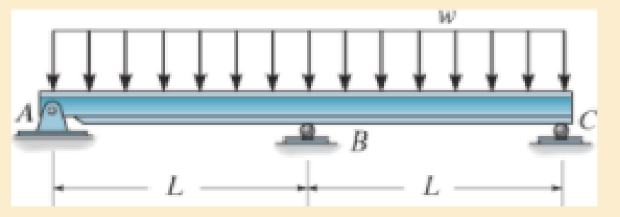
Chapter 12.9, Problem 12.118P
Determine the reactions at the supports, then draw the shear and moment diagrams. El is constant.
Expert Solution & Answer
Want to see the full answer?
Check out a sample textbook solution
Students have asked these similar questions
this is an old practice exam, the answer is Ax = -4, Ay = -12,Az = 32.5, Bx= 34, Bz = 5, By = 0 but how?
This is an old practice exam, the answer is Ax = Az = 0, Ay = 2000, TDE = 4750, Cx = 2000, Cy = 2000, Cz = -800 but how?
this is an old practice exam, the answer is Fmin = 290.5lb but how
Chapter 12 Solutions
Mechanics of Materials (10th Edition)
Ch. 12.2 - In each case, determine the internal bending...Ch. 12.2 - Determine the slope and deflection of end A of the...Ch. 12.2 - Determine the slope and deflection of end A of the...Ch. 12.2 - Determine the slope of end A of the cantilevered...Ch. 12.2 - Determine the maximum deflection of the simply...Ch. 12.2 - Determine the maximum deflection of the simply...Ch. 12.2 - Determine the slope of the simply supported beam...Ch. 12.2 - An L2 steel strap having a thickness of 0.125 in....Ch. 12.2 - The L2 steel blade of the band saw wraps around...Ch. 12.2 - A picture is taken of a man performing a pole...
Ch. 12.2 - El is constant. Prob. 124Ch. 12.2 - Determine the deflection of end C of the...Ch. 12.2 - Determine the elastic curve for the cantilevered...Ch. 12.2 - The A-36 steel beam has a depth of 10 in. and is...Ch. 12.2 - Determine the equations of the elastic curve using...Ch. 12.2 - Determine the equations of the elastic curve for...Ch. 12.2 - Determine the equations of the elastic curve using...Ch. 12.2 - Determine the equations of the elastic curve using...Ch. 12.2 - Draw the bending-moment diagram for the shaft and...Ch. 12.2 - Determine the maximum deflection of the beam and...Ch. 12.2 - The simply supported shaft has a moment of inertia...Ch. 12.2 - A torque wrench is used to tighten the nut on a...Ch. 12.2 - The pipe can be assumed roller supported at its...Ch. 12.2 - Determine the equations of the elastic curve for...Ch. 12.2 - The bar is supported by a roller constraint at B,...Ch. 12.2 - Determine the deflection at B of the bar in Prob....Ch. 12.2 - Determine the equations of the elastic curve using...Ch. 12.2 - Determine the maximum deflection of the solid...Ch. 12.2 - Determine the elastic curve for the cantilevered...Ch. 12.2 - Determine the equations of the elastic curve using...Ch. 12.2 - Determine the equations of the elastic curve using...Ch. 12.2 - The floor beam of the airplane is subjected to the...Ch. 12.2 - Determine the maximum deflection of the simply...Ch. 12.2 - The beam is made of a material having a specific...Ch. 12.2 - Determine the slope at end B and the maximum...Ch. 12.2 - Determine the equation of the elastic curve using...Ch. 12.2 - Determine the equations of the elastic curve using...Ch. 12.3 - The shaft is supported at A by a journal bearing...Ch. 12.3 - The shaft supports the two pulley loads shown....Ch. 12.3 - The beam is made of a ceramic material. If it is...Ch. 12.3 - Determine the equation of the elastic curve, the...Ch. 12.3 - The beam is subjected to the load shown. Determine...Ch. 12.3 - Determine the equation of the elastic curve, the...Ch. 12.3 - Determine the equation of the elastic curve and...Ch. 12.3 - The shaft supports the two pulley loads. Determine...Ch. 12.3 - Determine the maximum deflection of the...Ch. 12.3 - Determine the slope at A and the deflection of end...Ch. 12.3 - Determine the maximum deflection in region AB of...Ch. 12.3 - Prob. 12.42PCh. 12.3 - Prob. 12.43PCh. 12.3 - Prob. 12.44PCh. 12.3 - Prob. 12.45PCh. 12.3 - Prob. 12.46PCh. 12.3 - Prob. 12.47PCh. 12.3 - Determine the value of a so that the displacement...Ch. 12.3 - Determine the displacement at C and the slope at...Ch. 12.3 - Determine the equations of the slope and elastic...Ch. 12.4 - Determine the slope and deflection of end A of the...Ch. 12.4 - Determine the slope and deflection of end A of the...Ch. 12.4 - Determine the slope and deflection of end A of the...Ch. 12.4 - Determine the slope and deflection at A of the...Ch. 12.4 - Prob. 12.11FPCh. 12.4 - Determine the maximum deflection of the simply...Ch. 12.4 - Determine the slope and deflection at C. El is...Ch. 12.4 - Determine the slope and deflection at C. El is...Ch. 12.4 - Determine the deflection of end B of the...Ch. 12.4 - Prob. 12.54PCh. 12.4 - The composite simply supported steel shaft is...Ch. 12.4 - Prob. 12.56PCh. 12.4 - Prob. 12.57PCh. 12.4 - Determine the deflection at C and the slope of the...Ch. 12.4 - Determine the maximum deflection of the...Ch. 12.4 - Prob. 12.60PCh. 12.4 - Determine the position a of the roller support B...Ch. 12.4 - Prob. 12.62PCh. 12.4 - Determine the slope and the deflection of end B of...Ch. 12.4 - The two A-36 steel bars have a thickness of 1 in....Ch. 12.4 - Determine the slope at A and the displacement at...Ch. 12.4 - Determine the deflection at C and the slopes at...Ch. 12.4 - Determine the maximum deflection within region AB....Ch. 12.4 - Determine the slope at A and the maximum...Ch. 12.4 - Determine the slope at C and the deflection at B....Ch. 12.4 - Determine the slope at A and the maximum...Ch. 12.4 - Determine the displacement of the 20-mm-diameter...Ch. 12.4 - The two force components act on the tire of the...Ch. 12.4 - Prob. 12.73PCh. 12.4 - The rod is constructed from two shafts for which...Ch. 12.4 - Prob. 12.75PCh. 12.4 - Determine the slope at point A and the maximum...Ch. 12.4 - Determine the position a of roller support B in...Ch. 12.4 - Determine the slope at B and deflection at C. El...Ch. 12.4 - Prob. 12.79PCh. 12.4 - Prob. 12.80PCh. 12.4 - Prob. 12.81PCh. 12.4 - Determine the maximum deflection of the beam. El...Ch. 12.5 - The W10 15 cantilevered beam is made of A-36...Ch. 12.5 - The W10 15 cantilevered beam is made of A-36...Ch. 12.5 - The W14 43 simply supported beam is made of A992...Ch. 12.5 - The W14 43 simply supported beam is made of A992...Ch. 12.5 - The W14 43 simply supported beam is made of A-36...Ch. 12.5 - The W14 43 simply supported beam is made of A-36...Ch. 12.5 - The W8 48 cantilevered beam is made of A-36 steel...Ch. 12.5 - The beam supports the loading shown. Code...Ch. 12.5 - The W24 104 A-36 steel beam is used to support...Ch. 12.5 - The W8 48 cantilevered beam is made of A-36 steel...Ch. 12.5 - The rod is pinned at its end A and attached to a...Ch. 12.5 - Prob. 12.94PCh. 12.5 - The pipe assembly consists of three equal-sized...Ch. 12.5 - The assembly consists of a cantilevered beam CS...Ch. 12.5 - Determine the smallest force F required to attract...Ch. 12.5 - Prob. 12.98PCh. 12.7 - Determine the reactions at the supports A and B,...Ch. 12.7 - Determine the reactions at the supports, then draw...Ch. 12.7 - Determine the reactions at the supports A, B, and...Ch. 12.7 - Determine the reactions at the supports A and B,...Ch. 12.7 - Determine the reactions at the supports A and B,...Ch. 12.7 - Determine the moment reactions at the supports A...Ch. 12.7 - Determine the reactions at the supports A and B,...Ch. 12.7 - Determine the reactions at the support A and B. EI...Ch. 12.7 - Determine the reactions at roller support A and...Ch. 12.7 - Determine the moment reactions at the supports A...Ch. 12.7 - The beam has a constant E1I1 and is supported by...Ch. 12.7 - The beam is supported by a pin at A, a roller at...Ch. 12.8 - Determine the moment reactions at the supports A...Ch. 12.8 - Determine the reaction at the supports, then draw...Ch. 12.8 - Determine the vertical reaction at the journal...Ch. 12.8 - Determine the reactions at the supports A and B,...Ch. 12.8 - Determine the reactions at the supports. EI is...Ch. 12.8 - Determine the vertical reaction at the journal...Ch. 12.9 - Determine the reactions at the fixed support A and...Ch. 12.9 - Determine the reactions at the fixed support A and...Ch. 12.9 - Determine the reactions at the fixed support A and...Ch. 12.9 - Determine the reaction at the roller B. EI is...Ch. 12.9 - Determine the reaction at the roller B. EI is...Ch. 12.9 - Determine the reaction at the roller support B if...Ch. 12.9 - Determine the reactions at the journal bearing...Ch. 12.9 - Determine the reactions at the supports, then draw...Ch. 12.9 - Determine the reactions at the supports, then draw...Ch. 12.9 - Determine the reactions at the supports A and B....Ch. 12.9 - The beam is used to support the 20-kip load....Ch. 12.9 - Determine the reactions at the supports A and B....Ch. 12.9 - Determine the reactions at the supports A and B....Ch. 12.9 - Before the uniform distributed load is applied to...Ch. 12.9 - The fixed supported beam AB is strengthened using...Ch. 12.9 - The beam has a constant E1I1, and is supported by...Ch. 12.9 - The beam is supported by the bolted supports at...Ch. 12.9 - Each of the two members is made from 6061-T6...Ch. 12.9 - The beam is made from a soft linear elastic...Ch. 12.9 - The beam AB has a moment of inertia I = 475 in4...Ch. 12.9 - The rim on the flywheel has a thickness t, width...Ch. 12.9 - Determine the moment developed in each corner....Ch. 12 - Determine the equation of the elastic curve. Use...Ch. 12 - Draw the bending-moment diagram for the shaft and...Ch. 12 - Determine the moment reactions at the supports A...Ch. 12 - Specify the slope at A and the maximum deflection....Ch. 12 - Determine the maximum deflection between the...Ch. 12 - Determine the slope at B and the deflection at C....Ch. 12 - Determine the reactions, then draw the shear and...Ch. 12 - El is constant.Ch. 12 - Using the method of superposition, determine the...
Knowledge Booster


Learn more about
Need a deep-dive on the concept behind this application? Look no further. Learn more about this topic, mechanical-engineering and related others by exploring similar questions and additional content below.Similar questions
- This is an exam review question. The answer is Pmin = 622.9 lb but whyarrow_forwardPlease do not use any AI tools to solve this question. I need a fully manual, step-by-step solution with clear explanations, as if it were done by a human tutor. No AI-generated responses, please.arrow_forwardPlease do not use any AI tools to solve this question. I need a fully manual, step-by-step solution with clear explanations, as if it were done by a human tutor. No AI-generated responses, please.arrow_forward
- Please do not use any AI tools to solve this question. I need a fully manual, step-by-step solution with clear explanations, as if it were done by a human tutor. No AI-generated responses, please.arrow_forwardThis is an old practice exam. Fce = 110lb and FBCD = 62 lb but whyarrow_forwardQuiz/An eccentrically loaded bracket is welded to the support as shown in Figure below. The load is static. The weld size for weld w1 is h1 = 4mm, for w2 h2 = 6mm, and for w3 is h3 =6.5 mm. Determine the safety factor (S.f) for the welds. F=29 kN. Use an AWS Electrode type (E100xx). 163 mm S 133 mm 140 mm Please solve the question above I solved the question but I'm sure the answer is wrong the link : https://drive.google.com/file/d/1w5UD2EPDiaKSx3W33aj Rv0olChuXtrQx/view?usp=sharingarrow_forward
- Q2: (15 Marks) A water-LiBr vapor absorption system incorporates a heat exchanger as shown in the figure. The temperatures of the evaporator, the absorber, the condenser, and the generator are 10°C, 25°C, 40°C, and 100°C respectively. The strong liquid leaving the pump is heated to 50°C in the heat exchanger. The refrigerant flow rate through the condenser is 0.12 kg/s. Calculate (i) the heat rejected in the absorber, and (ii) the COP of the cycle. Yo 8 XE-V lo 9 Pc 7 condenser 5 Qgen PG 100 Qabs Pe evaporator PRV 6 PA 10 3 generator heat exchanger 2 pump 185 absorberarrow_forwardQ5:(? Design the duct system of the figure below by using the balanced pressure method. The velocity in the duct attached to the AHU must not exceed 5m/s. The pressure loss for each diffuser is equal to 10Pa. 100CFM 100CFM 100CFM ☑ ☑ 40m AHU -16m- 8m- -12m- 57m 250CFM 40m -14m- 26m 36m ☑ 250CFMarrow_forwardA mass of ideal gas in a closed piston-cylinder system expands from 427 °C and 16 bar following the process law, pv1.36 = Constant (p times v to the power of 1.36 equals to a constant). For the gas, initial : final pressure ratio is 4:1 and the initial gas volume is 0.14 m³. The specific heat of the gas at constant pressure, Cp = 0.987 kJ/kg-K and the specific gas constant, R = 0.267 kJ/kg.K. Determine the change in total internal energy in the gas during the expansion. Enter your numerical answer in the answer box below in KILO JOULES (not in Joules) but do not enter the units. (There is no expected number of decimal points or significant figures).arrow_forward
- my ID# 016948724. Please solve this problem step by steparrow_forwardMy ID# 016948724 please find the forces for Fx=0: fy=0: fz=0: please help me to solve this problem step by steparrow_forwardMy ID# 016948724 please solve the proble step by step find the forces fx=o: fy=0; fz=0; and find shear moment and the bending moment diagran please draw the diagram for the shear and bending momentarrow_forward
arrow_back_ios
SEE MORE QUESTIONS
arrow_forward_ios
Recommended textbooks for you
 Mechanics of Materials (MindTap Course List)Mechanical EngineeringISBN:9781337093347Author:Barry J. Goodno, James M. GerePublisher:Cengage Learning
 International Edition---engineering Mechanics: St...Mechanical EngineeringISBN:9781305501607Author:Andrew Pytel And Jaan KiusalaasPublisher:CENGAGE L
Mechanics of Materials (MindTap Course List)
Mechanical Engineering
ISBN:9781337093347
Author:Barry J. Goodno, James M. Gere
Publisher:Cengage Learning
International Edition---engineering Mechanics: St...
Mechanical Engineering
ISBN:9781305501607
Author:Andrew Pytel And Jaan Kiusalaas
Publisher:CENGAGE L
Understanding Shear Force and Bending Moment Diagrams; Author: The Efficient Engineer;https://www.youtube.com/watch?v=C-FEVzI8oe8;License: Standard YouTube License, CC-BY
Bending Stress; Author: moodlemech;https://www.youtube.com/watch?v=9QIqewkE6xM;License: Standard Youtube License