
Mechanics of Materials (10th Edition)
10th Edition
ISBN: 9780134319650
Author: Russell C. Hibbeler
Publisher: PEARSON
expand_more
expand_more
format_list_bulleted
Videos
Textbook Question
Chapter 12.2, Problem 12.1PP
In each case, determine the internal bending moment as a function of x, and state the necessary boundary and/or continuity conditions used to determine the elastic curve for the beam.
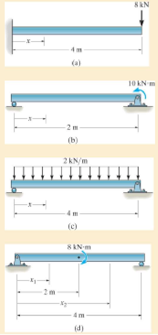
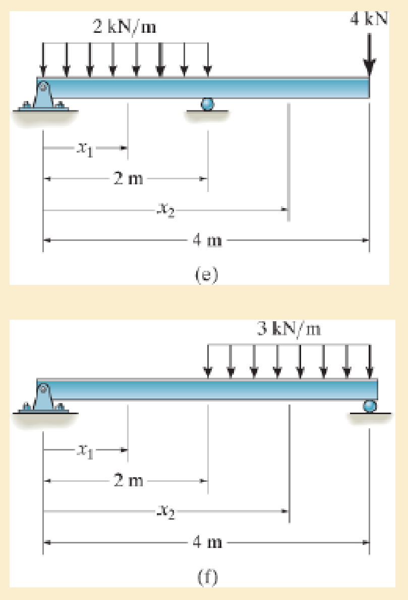
Prob. 12–1
Expert Solution & Answer

Learn your wayIncludes step-by-step video

schedule26:56
Students have asked these similar questions
I want the steps of operation of the circuit, clearly in
detail. Please.
LV1
Complet the solution:
Vavg Ti Te Ts Qhexp Nuexp htheo Re Nutheo Error
(m/s) (°C) (°C) (°C)
(W)
2.11 18.8 21.3 45.8
2.61 18.5 20.8 46.3
Heat transfer
Given data:
a= 10 cm.
L= 10 cm.
b= 20 cm.
H=40cm.
⚫ a = 10, cm: This could represent the width of the duct.
⚫b=20, cm: This might be the height of the duct.
⚫L = 10, cm: This usually stands for the length of the duct in
the direction of flow.
⚫H=40, cm: This could indicate the height of some
component or another duct-related dimension, but the exact
meaning depends on the experiment's context.
please explain each step and include drawings on the phase diagram. thanks
Chapter 12 Solutions
Mechanics of Materials (10th Edition)
Ch. 12.2 - In each case, determine the internal bending...Ch. 12.2 - Determine the slope and deflection of end A of the...Ch. 12.2 - Determine the slope and deflection of end A of the...Ch. 12.2 - Determine the slope of end A of the cantilevered...Ch. 12.2 - Determine the maximum deflection of the simply...Ch. 12.2 - Determine the maximum deflection of the simply...Ch. 12.2 - Determine the slope of the simply supported beam...Ch. 12.2 - An L2 steel strap having a thickness of 0.125 in....Ch. 12.2 - The L2 steel blade of the band saw wraps around...Ch. 12.2 - A picture is taken of a man performing a pole...
Ch. 12.2 - El is constant. Prob. 124Ch. 12.2 - Determine the deflection of end C of the...Ch. 12.2 - Determine the elastic curve for the cantilevered...Ch. 12.2 - The A-36 steel beam has a depth of 10 in. and is...Ch. 12.2 - Determine the equations of the elastic curve using...Ch. 12.2 - Determine the equations of the elastic curve for...Ch. 12.2 - Determine the equations of the elastic curve using...Ch. 12.2 - Determine the equations of the elastic curve using...Ch. 12.2 - Draw the bending-moment diagram for the shaft and...Ch. 12.2 - Determine the maximum deflection of the beam and...Ch. 12.2 - The simply supported shaft has a moment of inertia...Ch. 12.2 - A torque wrench is used to tighten the nut on a...Ch. 12.2 - The pipe can be assumed roller supported at its...Ch. 12.2 - Determine the equations of the elastic curve for...Ch. 12.2 - The bar is supported by a roller constraint at B,...Ch. 12.2 - Determine the deflection at B of the bar in Prob....Ch. 12.2 - Determine the equations of the elastic curve using...Ch. 12.2 - Determine the maximum deflection of the solid...Ch. 12.2 - Determine the elastic curve for the cantilevered...Ch. 12.2 - Determine the equations of the elastic curve using...Ch. 12.2 - Determine the equations of the elastic curve using...Ch. 12.2 - The floor beam of the airplane is subjected to the...Ch. 12.2 - Determine the maximum deflection of the simply...Ch. 12.2 - The beam is made of a material having a specific...Ch. 12.2 - Determine the slope at end B and the maximum...Ch. 12.2 - Determine the equation of the elastic curve using...Ch. 12.2 - Determine the equations of the elastic curve using...Ch. 12.3 - The shaft is supported at A by a journal bearing...Ch. 12.3 - The shaft supports the two pulley loads shown....Ch. 12.3 - The beam is made of a ceramic material. If it is...Ch. 12.3 - Determine the equation of the elastic curve, the...Ch. 12.3 - The beam is subjected to the load shown. Determine...Ch. 12.3 - Determine the equation of the elastic curve, the...Ch. 12.3 - Determine the equation of the elastic curve and...Ch. 12.3 - The shaft supports the two pulley loads. Determine...Ch. 12.3 - Determine the maximum deflection of the...Ch. 12.3 - Determine the slope at A and the deflection of end...Ch. 12.3 - Determine the maximum deflection in region AB of...Ch. 12.3 - Prob. 12.42PCh. 12.3 - Prob. 12.43PCh. 12.3 - Prob. 12.44PCh. 12.3 - Prob. 12.45PCh. 12.3 - Prob. 12.46PCh. 12.3 - Prob. 12.47PCh. 12.3 - Determine the value of a so that the displacement...Ch. 12.3 - Determine the displacement at C and the slope at...Ch. 12.3 - Determine the equations of the slope and elastic...Ch. 12.4 - Determine the slope and deflection of end A of the...Ch. 12.4 - Determine the slope and deflection of end A of the...Ch. 12.4 - Determine the slope and deflection of end A of the...Ch. 12.4 - Determine the slope and deflection at A of the...Ch. 12.4 - Prob. 12.11FPCh. 12.4 - Determine the maximum deflection of the simply...Ch. 12.4 - Determine the slope and deflection at C. El is...Ch. 12.4 - Determine the slope and deflection at C. El is...Ch. 12.4 - Determine the deflection of end B of the...Ch. 12.4 - Prob. 12.54PCh. 12.4 - The composite simply supported steel shaft is...Ch. 12.4 - Prob. 12.56PCh. 12.4 - Prob. 12.57PCh. 12.4 - Determine the deflection at C and the slope of the...Ch. 12.4 - Determine the maximum deflection of the...Ch. 12.4 - Prob. 12.60PCh. 12.4 - Determine the position a of the roller support B...Ch. 12.4 - Prob. 12.62PCh. 12.4 - Determine the slope and the deflection of end B of...Ch. 12.4 - The two A-36 steel bars have a thickness of 1 in....Ch. 12.4 - Determine the slope at A and the displacement at...Ch. 12.4 - Determine the deflection at C and the slopes at...Ch. 12.4 - Determine the maximum deflection within region AB....Ch. 12.4 - Determine the slope at A and the maximum...Ch. 12.4 - Determine the slope at C and the deflection at B....Ch. 12.4 - Determine the slope at A and the maximum...Ch. 12.4 - Determine the displacement of the 20-mm-diameter...Ch. 12.4 - The two force components act on the tire of the...Ch. 12.4 - Prob. 12.73PCh. 12.4 - The rod is constructed from two shafts for which...Ch. 12.4 - Prob. 12.75PCh. 12.4 - Determine the slope at point A and the maximum...Ch. 12.4 - Determine the position a of roller support B in...Ch. 12.4 - Determine the slope at B and deflection at C. El...Ch. 12.4 - Prob. 12.79PCh. 12.4 - Prob. 12.80PCh. 12.4 - Prob. 12.81PCh. 12.4 - Determine the maximum deflection of the beam. El...Ch. 12.5 - The W10 15 cantilevered beam is made of A-36...Ch. 12.5 - The W10 15 cantilevered beam is made of A-36...Ch. 12.5 - The W14 43 simply supported beam is made of A992...Ch. 12.5 - The W14 43 simply supported beam is made of A992...Ch. 12.5 - The W14 43 simply supported beam is made of A-36...Ch. 12.5 - The W14 43 simply supported beam is made of A-36...Ch. 12.5 - The W8 48 cantilevered beam is made of A-36 steel...Ch. 12.5 - The beam supports the loading shown. Code...Ch. 12.5 - The W24 104 A-36 steel beam is used to support...Ch. 12.5 - The W8 48 cantilevered beam is made of A-36 steel...Ch. 12.5 - The rod is pinned at its end A and attached to a...Ch. 12.5 - Prob. 12.94PCh. 12.5 - The pipe assembly consists of three equal-sized...Ch. 12.5 - The assembly consists of a cantilevered beam CS...Ch. 12.5 - Determine the smallest force F required to attract...Ch. 12.5 - Prob. 12.98PCh. 12.7 - Determine the reactions at the supports A and B,...Ch. 12.7 - Determine the reactions at the supports, then draw...Ch. 12.7 - Determine the reactions at the supports A, B, and...Ch. 12.7 - Determine the reactions at the supports A and B,...Ch. 12.7 - Determine the reactions at the supports A and B,...Ch. 12.7 - Determine the moment reactions at the supports A...Ch. 12.7 - Determine the reactions at the supports A and B,...Ch. 12.7 - Determine the reactions at the support A and B. EI...Ch. 12.7 - Determine the reactions at roller support A and...Ch. 12.7 - Determine the moment reactions at the supports A...Ch. 12.7 - The beam has a constant E1I1 and is supported by...Ch. 12.7 - The beam is supported by a pin at A, a roller at...Ch. 12.8 - Determine the moment reactions at the supports A...Ch. 12.8 - Determine the reaction at the supports, then draw...Ch. 12.8 - Determine the vertical reaction at the journal...Ch. 12.8 - Determine the reactions at the supports A and B,...Ch. 12.8 - Determine the reactions at the supports. EI is...Ch. 12.8 - Determine the vertical reaction at the journal...Ch. 12.9 - Determine the reactions at the fixed support A and...Ch. 12.9 - Determine the reactions at the fixed support A and...Ch. 12.9 - Determine the reactions at the fixed support A and...Ch. 12.9 - Determine the reaction at the roller B. EI is...Ch. 12.9 - Determine the reaction at the roller B. EI is...Ch. 12.9 - Determine the reaction at the roller support B if...Ch. 12.9 - Determine the reactions at the journal bearing...Ch. 12.9 - Determine the reactions at the supports, then draw...Ch. 12.9 - Determine the reactions at the supports, then draw...Ch. 12.9 - Determine the reactions at the supports A and B....Ch. 12.9 - The beam is used to support the 20-kip load....Ch. 12.9 - Determine the reactions at the supports A and B....Ch. 12.9 - Determine the reactions at the supports A and B....Ch. 12.9 - Before the uniform distributed load is applied to...Ch. 12.9 - The fixed supported beam AB is strengthened using...Ch. 12.9 - The beam has a constant E1I1, and is supported by...Ch. 12.9 - The beam is supported by the bolted supports at...Ch. 12.9 - Each of the two members is made from 6061-T6...Ch. 12.9 - The beam is made from a soft linear elastic...Ch. 12.9 - The beam AB has a moment of inertia I = 475 in4...Ch. 12.9 - The rim on the flywheel has a thickness t, width...Ch. 12.9 - Determine the moment developed in each corner....Ch. 12 - Determine the equation of the elastic curve. Use...Ch. 12 - Draw the bending-moment diagram for the shaft and...Ch. 12 - Determine the moment reactions at the supports A...Ch. 12 - Specify the slope at A and the maximum deflection....Ch. 12 - Determine the maximum deflection between the...Ch. 12 - Determine the slope at B and the deflection at C....Ch. 12 - Determine the reactions, then draw the shear and...Ch. 12 - El is constant.Ch. 12 - Using the method of superposition, determine the...
Additional Engineering Textbook Solutions
Find more solutions based on key concepts
For the circuit shown, find (a) the voltage υ, (b) the power delivered to the circuit by the current source, an...
Electric Circuits. (11th Edition)
F416. Determine the magnitude of the moment of the force about the y axis. F = {30i 20j + 50k} N
INTERNATIONAL EDITION---Engineering Mechanics: Statics, 14th edition (SI unit)
This marks the location of the next item that will be read from a file. a. input position b. delimiter c. point...
Starting Out with Python (4th Edition)
What is the nature of the surface obtained by electrodischarge machining (EDM)?
Degarmo's Materials And Processes In Manufacturing
What is an object? What is a control?
Starting Out With Visual Basic (8th Edition)
Why is the study of database technology important?
Database Concepts (8th Edition)
Knowledge Booster


Learn more about
Need a deep-dive on the concept behind this application? Look no further. Learn more about this topic, mechanical-engineering and related others by exploring similar questions and additional content below.Similar questions
- Write clearly which points correspond to concentration of solute in front of alpha, concentration of solute in front of beta, amount of solid in the liquid in front of alpha/beta, lowest possible energy (tangent), as well as any other important information. Thank youarrow_forwardQ3: A 4-stroke 6 litres engine is fuelled with methane (CH4) at an air-fuel ratio = 0.8. It operates at 2000 rpm with a volumetric efficiency of 80%. The exhaust (product) leaves the engine at 800 K, and the heat lost to the coolant is 3.4×10⁵ kJ/kmol. What is the engine's output power? Assume both air and fuel (methane) inlet to the engine at 298 K. Take for methane, the molecular weight is M = 16 kg/kmol, and the heat of combustion is 50.01 MJ/kg. The ambient conditions (p = 101 kPa, T = 25 °C). (24 points)arrow_forwardTemperature (°C) 100 4. Consider the solidification of a binary Pb-10%Sn alloy. Assume that during solidification, there is complete mixing in the liquid and no diffusion in the solid. Use the phase diagram below to answer the following question. (a) Draw (on the phase diagram) the compositions of the liquid and the solid at the interface as a function of temperature during solidification. (b) Illustrate on the phase diagram how one would calculate the volume fraction solidified at a given temperature. (c) (d) Indicate the temperature at which solidification is complete. Do you expect ẞ to be present in the as-cast microstructure? Explain 300 327°C 200 a (Pb) 20 20 a + L 18.3 183°C α + β 40 60 Composition (wt% Sn) Liquid 600 500 232°C B+L 400 B 61.9 97.8 300 808 100 (Sn) 200 100 Temperature (°F)arrow_forward
- I tried this problem a couple of times and don't know where I'm going wrong can you help me out pleasearrow_forwardy(0)=1, Using Laplace transforms solve the following differential equations : 11) y"-4y+4y=0, 12) y+2y+2y=0, y(0)=2.1, y'(0) = 3.9 y'(0)=-3. 13) y+7y+12y=21e", y(0)=3.5, y'(0)=-10. 14) +9y=10e. y(0)=0, y'(0) = 0. 15) y+3y+2.25y=91³ +64, y(0)=1, y'(0) = 31.5 16) -6y+5y= 29 cos(21), y(0)=3.2, y'(0)=6.2 17) "+2y+2y=0, y(0)=0, y'(0)=1. 18) +2y+17y=0, y(0)=0, y'(0)=12. 19) y-4y+5y=0, y(0)=1, y'(0) = 2. 20) 9y-6y+y=0, y(0)=3, y'(0)=1. 21) -2y+10y=0, y(0)=3, y'(0)=3.arrow_forward4. Consider the rectangulan 2535 Let 16 a and section discussed 977b + class. in ie make a M thin" rectangle, Can you you show that Q = Go {a² = x² } . Imax = 2 Ga ты J =arrow_forward
- 1. Consider a circular shaft in torsion that of radius r=b has a key way as shown, circle of radius a Let us try the solution x₁ (5,0) = k (6² = r²) (1- 2 awso 1.1 Does this solve the problem for the stres rer 1,2 Solve for is and 23.arrow_forward3. - a For an elliptical cross that the tangent to section resultant shear can you s stress is show ellipse with the same 24 i ratio of eccentricity, in passes through to point alb that in question, it + Parrow_forward2. Consider the rod with an elliptical that strain 4 a Cross secton considered in class, Integrate the was displacement displacements, relations to obtain thearrow_forward
- Please answer Oxygen at 300 kPa and 90°C flowing at an average velocity of 3 m/s is expanded in an adiabatic nozzle. What is the maximum velocity of the oxygen at the outlet of this nozzle when the outlet pressure is 60 kPa? Use the table containing the ideal gas specific heats of various common gases. The maximum velocity of the oxygen at the outlet of this nozzle is 532.5 Numeric ResponseEdit Unavailable. 532.5 incorrect.m/s.arrow_forwardA container filled with 70 kg of liquid water at 95°C is placed in a 90-m3 room that is initially at 12°C. Thermal equilibrium is established after a while as a result of heat transfer between the water and the air in the room. Assume the room is at the sea level, well sealed, and heavily insulated. NOTE: This is a multi-part question. Once an answer is submitted, you will be unable to return to this part. Determine the amount of heat transfer between the water and the air in the room. The amount of heat transfer between the water and the air in the room is kJ.arrow_forwardA strain gauge rosette that is attached to the surface of a stressed component gives 3 readings (ɛa = A, b = B, &c = C). If the strain gauge rosette is of the D° type (indicating the angle between each of the gauges), construct a Mohr's Strain Circle overleaf. You should assume that gauge A is aligned along the x-axis. Using the Mohr's Strain Circle calculate the: (i) principal strains (ε1, 2)? (ii) principal angles (1, 2)? You should measure these anticlockwise from the y-axis. (iii) maximum shear strain in the plane (ymax)?arrow_forward
arrow_back_ios
SEE MORE QUESTIONS
arrow_forward_ios
Recommended textbooks for you
 Elements Of ElectromagneticsMechanical EngineeringISBN:9780190698614Author:Sadiku, Matthew N. O.Publisher:Oxford University Press
 Mechanics of Materials (10th Edition)Mechanical EngineeringISBN:9780134319650Author:Russell C. HibbelerPublisher:PEARSON
 Thermodynamics: An Engineering ApproachMechanical EngineeringISBN:9781259822674Author:Yunus A. Cengel Dr., Michael A. BolesPublisher:McGraw-Hill Education
 Control Systems EngineeringMechanical EngineeringISBN:9781118170519Author:Norman S. NisePublisher:WILEY
 Mechanics of Materials (MindTap Course List)Mechanical EngineeringISBN:9781337093347Author:Barry J. Goodno, James M. GerePublisher:Cengage Learning
 Engineering Mechanics: StaticsMechanical EngineeringISBN:9781118807330Author:James L. Meriam, L. G. Kraige, J. N. BoltonPublisher:WILEY
Elements Of Electromagnetics
Mechanical Engineering
ISBN:9780190698614
Author:Sadiku, Matthew N. O.
Publisher:Oxford University Press
Mechanics of Materials (10th Edition)
Mechanical Engineering
ISBN:9780134319650
Author:Russell C. Hibbeler
Publisher:PEARSON
Thermodynamics: An Engineering Approach
Mechanical Engineering
ISBN:9781259822674
Author:Yunus A. Cengel Dr., Michael A. Boles
Publisher:McGraw-Hill Education
Control Systems Engineering
Mechanical Engineering
ISBN:9781118170519
Author:Norman S. Nise
Publisher:WILEY
Mechanics of Materials (MindTap Course List)
Mechanical Engineering
ISBN:9781337093347
Author:Barry J. Goodno, James M. Gere
Publisher:Cengage Learning
Engineering Mechanics: Statics
Mechanical Engineering
ISBN:9781118807330
Author:James L. Meriam, L. G. Kraige, J. N. Bolton
Publisher:WILEY
Mechanics of Materials Lecture: Beam Design; Author: UWMC Engineering;https://www.youtube.com/watch?v=-wVs5pvQPm4;License: Standard Youtube License