
Mechanics of Materials (10th Edition)
10th Edition
ISBN: 9780134319650
Author: Russell C. Hibbeler
Publisher: PEARSON
expand_more
expand_more
format_list_bulleted
Concept explainers
Videos
Textbook Question
Chapter 12.3, Problem 12.49P
Determine the displacement at C and the slope at A. El is constant.
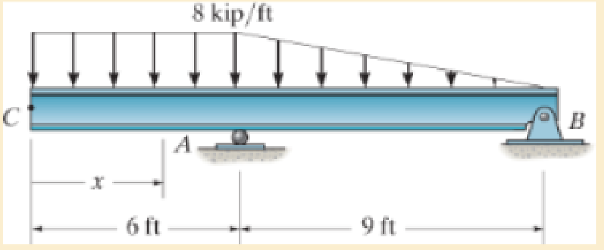
Prob. 12–49
Expert Solution & Answer
Want to see the full answer?
Check out a sample textbook solution
Students have asked these similar questions
(Read image) (Answer given)
Problem (17): water flowing in an open channel of a rectangular cross-section with width (b) transitions from a
mild slope to a steep slope (i.e., from subcritical to supercritical flow) with normal water depths of (y₁) and
(y2), respectively.
Given the values of y₁ [m], y₂ [m], and b [m], calculate the discharge in the channel (Q) in [Lit/s].
Givens:
y1 = 4.112 m
y2 =
0.387 m
b = 0.942 m
Answers:
( 1 ) 1880.186 lit/s
( 2 ) 4042.945 lit/s
( 3 ) 2553.11 lit/s
( 4 ) 3130.448 lit/s
Problem (14): A pump is being used to lift water from an underground
tank through a pipe of diameter (d) at discharge (Q). The total head
loss until the pump entrance can be calculated as (h₁ = K[V²/2g]), h
where (V) is the flow velocity in the pipe. The elevation difference
between the pump and tank surface is (h).
Given the values of h [cm], d [cm], and K [-], calculate the maximum
discharge Q [Lit/s] beyond which cavitation would take place at the
pump entrance. Assume Turbulent flow conditions.
Givens:
h = 120.31 cm
d = 14.455 cm
K = 8.976
Q
Answers:
(1) 94.917 lit/s
(2) 49.048 lit/s
( 3 ) 80.722 lit/s
68.588 lit/s
4
Chapter 12 Solutions
Mechanics of Materials (10th Edition)
Ch. 12.2 - In each case, determine the internal bending...Ch. 12.2 - Determine the slope and deflection of end A of the...Ch. 12.2 - Determine the slope and deflection of end A of the...Ch. 12.2 - Determine the slope of end A of the cantilevered...Ch. 12.2 - Determine the maximum deflection of the simply...Ch. 12.2 - Determine the maximum deflection of the simply...Ch. 12.2 - Determine the slope of the simply supported beam...Ch. 12.2 - An L2 steel strap having a thickness of 0.125 in....Ch. 12.2 - The L2 steel blade of the band saw wraps around...Ch. 12.2 - A picture is taken of a man performing a pole...
Ch. 12.2 - El is constant. Prob. 124Ch. 12.2 - Determine the deflection of end C of the...Ch. 12.2 - Determine the elastic curve for the cantilevered...Ch. 12.2 - The A-36 steel beam has a depth of 10 in. and is...Ch. 12.2 - Determine the equations of the elastic curve using...Ch. 12.2 - Determine the equations of the elastic curve for...Ch. 12.2 - Determine the equations of the elastic curve using...Ch. 12.2 - Determine the equations of the elastic curve using...Ch. 12.2 - Draw the bending-moment diagram for the shaft and...Ch. 12.2 - Determine the maximum deflection of the beam and...Ch. 12.2 - The simply supported shaft has a moment of inertia...Ch. 12.2 - A torque wrench is used to tighten the nut on a...Ch. 12.2 - The pipe can be assumed roller supported at its...Ch. 12.2 - Determine the equations of the elastic curve for...Ch. 12.2 - The bar is supported by a roller constraint at B,...Ch. 12.2 - Determine the deflection at B of the bar in Prob....Ch. 12.2 - Determine the equations of the elastic curve using...Ch. 12.2 - Determine the maximum deflection of the solid...Ch. 12.2 - Determine the elastic curve for the cantilevered...Ch. 12.2 - Determine the equations of the elastic curve using...Ch. 12.2 - Determine the equations of the elastic curve using...Ch. 12.2 - The floor beam of the airplane is subjected to the...Ch. 12.2 - Determine the maximum deflection of the simply...Ch. 12.2 - The beam is made of a material having a specific...Ch. 12.2 - Determine the slope at end B and the maximum...Ch. 12.2 - Determine the equation of the elastic curve using...Ch. 12.2 - Determine the equations of the elastic curve using...Ch. 12.3 - The shaft is supported at A by a journal bearing...Ch. 12.3 - The shaft supports the two pulley loads shown....Ch. 12.3 - The beam is made of a ceramic material. If it is...Ch. 12.3 - Determine the equation of the elastic curve, the...Ch. 12.3 - The beam is subjected to the load shown. Determine...Ch. 12.3 - Determine the equation of the elastic curve, the...Ch. 12.3 - Determine the equation of the elastic curve and...Ch. 12.3 - The shaft supports the two pulley loads. Determine...Ch. 12.3 - Determine the maximum deflection of the...Ch. 12.3 - Determine the slope at A and the deflection of end...Ch. 12.3 - Determine the maximum deflection in region AB of...Ch. 12.3 - Prob. 12.42PCh. 12.3 - Prob. 12.43PCh. 12.3 - Prob. 12.44PCh. 12.3 - Prob. 12.45PCh. 12.3 - Prob. 12.46PCh. 12.3 - Prob. 12.47PCh. 12.3 - Determine the value of a so that the displacement...Ch. 12.3 - Determine the displacement at C and the slope at...Ch. 12.3 - Determine the equations of the slope and elastic...Ch. 12.4 - Determine the slope and deflection of end A of the...Ch. 12.4 - Determine the slope and deflection of end A of the...Ch. 12.4 - Determine the slope and deflection of end A of the...Ch. 12.4 - Determine the slope and deflection at A of the...Ch. 12.4 - Prob. 12.11FPCh. 12.4 - Determine the maximum deflection of the simply...Ch. 12.4 - Determine the slope and deflection at C. El is...Ch. 12.4 - Determine the slope and deflection at C. El is...Ch. 12.4 - Determine the deflection of end B of the...Ch. 12.4 - Prob. 12.54PCh. 12.4 - The composite simply supported steel shaft is...Ch. 12.4 - Prob. 12.56PCh. 12.4 - Prob. 12.57PCh. 12.4 - Determine the deflection at C and the slope of the...Ch. 12.4 - Determine the maximum deflection of the...Ch. 12.4 - Prob. 12.60PCh. 12.4 - Determine the position a of the roller support B...Ch. 12.4 - Prob. 12.62PCh. 12.4 - Determine the slope and the deflection of end B of...Ch. 12.4 - The two A-36 steel bars have a thickness of 1 in....Ch. 12.4 - Determine the slope at A and the displacement at...Ch. 12.4 - Determine the deflection at C and the slopes at...Ch. 12.4 - Determine the maximum deflection within region AB....Ch. 12.4 - Determine the slope at A and the maximum...Ch. 12.4 - Determine the slope at C and the deflection at B....Ch. 12.4 - Determine the slope at A and the maximum...Ch. 12.4 - Determine the displacement of the 20-mm-diameter...Ch. 12.4 - The two force components act on the tire of the...Ch. 12.4 - Prob. 12.73PCh. 12.4 - The rod is constructed from two shafts for which...Ch. 12.4 - Prob. 12.75PCh. 12.4 - Determine the slope at point A and the maximum...Ch. 12.4 - Determine the position a of roller support B in...Ch. 12.4 - Determine the slope at B and deflection at C. El...Ch. 12.4 - Prob. 12.79PCh. 12.4 - Prob. 12.80PCh. 12.4 - Prob. 12.81PCh. 12.4 - Determine the maximum deflection of the beam. El...Ch. 12.5 - The W10 15 cantilevered beam is made of A-36...Ch. 12.5 - The W10 15 cantilevered beam is made of A-36...Ch. 12.5 - The W14 43 simply supported beam is made of A992...Ch. 12.5 - The W14 43 simply supported beam is made of A992...Ch. 12.5 - The W14 43 simply supported beam is made of A-36...Ch. 12.5 - The W14 43 simply supported beam is made of A-36...Ch. 12.5 - The W8 48 cantilevered beam is made of A-36 steel...Ch. 12.5 - The beam supports the loading shown. Code...Ch. 12.5 - The W24 104 A-36 steel beam is used to support...Ch. 12.5 - The W8 48 cantilevered beam is made of A-36 steel...Ch. 12.5 - The rod is pinned at its end A and attached to a...Ch. 12.5 - Prob. 12.94PCh. 12.5 - The pipe assembly consists of three equal-sized...Ch. 12.5 - The assembly consists of a cantilevered beam CS...Ch. 12.5 - Determine the smallest force F required to attract...Ch. 12.5 - Prob. 12.98PCh. 12.7 - Determine the reactions at the supports A and B,...Ch. 12.7 - Determine the reactions at the supports, then draw...Ch. 12.7 - Determine the reactions at the supports A, B, and...Ch. 12.7 - Determine the reactions at the supports A and B,...Ch. 12.7 - Determine the reactions at the supports A and B,...Ch. 12.7 - Determine the moment reactions at the supports A...Ch. 12.7 - Determine the reactions at the supports A and B,...Ch. 12.7 - Determine the reactions at the support A and B. EI...Ch. 12.7 - Determine the reactions at roller support A and...Ch. 12.7 - Determine the moment reactions at the supports A...Ch. 12.7 - The beam has a constant E1I1 and is supported by...Ch. 12.7 - The beam is supported by a pin at A, a roller at...Ch. 12.8 - Determine the moment reactions at the supports A...Ch. 12.8 - Determine the reaction at the supports, then draw...Ch. 12.8 - Determine the vertical reaction at the journal...Ch. 12.8 - Determine the reactions at the supports A and B,...Ch. 12.8 - Determine the reactions at the supports. EI is...Ch. 12.8 - Determine the vertical reaction at the journal...Ch. 12.9 - Determine the reactions at the fixed support A and...Ch. 12.9 - Determine the reactions at the fixed support A and...Ch. 12.9 - Determine the reactions at the fixed support A and...Ch. 12.9 - Determine the reaction at the roller B. EI is...Ch. 12.9 - Determine the reaction at the roller B. EI is...Ch. 12.9 - Determine the reaction at the roller support B if...Ch. 12.9 - Determine the reactions at the journal bearing...Ch. 12.9 - Determine the reactions at the supports, then draw...Ch. 12.9 - Determine the reactions at the supports, then draw...Ch. 12.9 - Determine the reactions at the supports A and B....Ch. 12.9 - The beam is used to support the 20-kip load....Ch. 12.9 - Determine the reactions at the supports A and B....Ch. 12.9 - Determine the reactions at the supports A and B....Ch. 12.9 - Before the uniform distributed load is applied to...Ch. 12.9 - The fixed supported beam AB is strengthened using...Ch. 12.9 - The beam has a constant E1I1, and is supported by...Ch. 12.9 - The beam is supported by the bolted supports at...Ch. 12.9 - Each of the two members is made from 6061-T6...Ch. 12.9 - The beam is made from a soft linear elastic...Ch. 12.9 - The beam AB has a moment of inertia I = 475 in4...Ch. 12.9 - The rim on the flywheel has a thickness t, width...Ch. 12.9 - Determine the moment developed in each corner....Ch. 12 - Determine the equation of the elastic curve. Use...Ch. 12 - Draw the bending-moment diagram for the shaft and...Ch. 12 - Determine the moment reactions at the supports A...Ch. 12 - Specify the slope at A and the maximum deflection....Ch. 12 - Determine the maximum deflection between the...Ch. 12 - Determine the slope at B and the deflection at C....Ch. 12 - Determine the reactions, then draw the shear and...Ch. 12 - El is constant.Ch. 12 - Using the method of superposition, determine the...
Additional Engineering Textbook Solutions
Find more solutions based on key concepts
Convert each of the following binary representations to its equivalent base ten form: a. 101010 b. 100001 c. 10...
Computer Science: An Overview (13th Edition) (What's New in Computer Science)
CONCEPT QUESTIONS
15.CQ3 The ball rolls without slipping on the fixed surface as shown. What is the direction ...
Vector Mechanics for Engineers: Statics and Dynamics
How is the hydrodynamic entry length defined for flow in a pipe? Is the entry length longer in laminar or turbu...
Fluid Mechanics: Fundamentals and Applications
Write a summary list of the problem-solving steps identified in the chapter, using your own words.
BASIC BIOMECHANICS
Assume a telephone signal travels through a cable at two-thirds the speed of light. How long does it take the s...
Electric Circuits. (11th Edition)
Knowledge Booster


Learn more about
Need a deep-dive on the concept behind this application? Look no further. Learn more about this topic, mechanical-engineering and related others by exploring similar questions and additional content below.Similar questions
- Problem (13): A pump is being used to lift water from the bottom tank to the top tank in a galvanized iron pipe at a discharge (Q). The length and diameter of the pipe section from the bottom tank to the pump are (L₁) and (d₁), respectively. The length and diameter of the pipe section from the pump to the top tank are (L2) and (d2), respectively. Given the values of Q [L/s], L₁ [m], d₁ [m], L₂ [m], d₂ [m], calculate total head loss due to friction (i.e., major loss) in the pipe (hmajor-loss) in [cm]. Givens: L₁,d₁ Pump L₂,d2 오 0.533 lit/s L1 = 6920.729 m d1 = 1.065 m L2 = 70.946 m d2 0.072 m Answers: (1) 3.069 cm (2) 3.914 cm ( 3 ) 2.519 cm ( 4 ) 1.855 cm TABLE 8.1 Equivalent Roughness for New Pipes Pipe Riveted steel Concrete Wood stave Cast iron Galvanized iron Equivalent Roughness, & Feet Millimeters 0.003-0.03 0.9-9.0 0.001-0.01 0.3-3.0 0.0006-0.003 0.18-0.9 0.00085 0.26 0.0005 0.15 0.045 0.000005 0.0015 0.0 (smooth) 0.0 (smooth) Commercial steel or wrought iron 0.00015 Drawn…arrow_forwardThe flow rate is 12.275 Liters/s and the diameter is 6.266 cm.arrow_forwardAn experimental setup is being built to study the flow in a large water main (i.e., a large pipe). The water main is expected to convey a discharge (Qp). The experimental tube will be built at a length scale of 1/20 of the actual water main. After building the experimental setup, the pressure drop per unit length in the model tube (APm/Lm) is measured. Problem (20): Given the value of APm/Lm [kPa/m], and assuming pressure coefficient similitude, calculate the drop in the pressure per unit length of the water main (APP/Lp) in [Pa/m]. Givens: AP M/L m = 590.637 kPa/m meen Answers: ( 1 ) 59.369 Pa/m ( 2 ) 73.83 Pa/m (3) 95.443 Pa/m ( 4 ) 44.444 Pa/m *******arrow_forward
- Find the reaction force in y if Ain = 0.169 m^2, Aout = 0.143 m^2, p_in = 0.552 atm, Q = 0.367 m^3/s, α = 31.72 degrees. The pipe is flat on the ground so do not factor in weight of the pipe and fluid.arrow_forwardFind the reaction force in x if Ain = 0.301 m^2, Aout = 0.177 m^2, p_in = 1.338 atm, Q = 0.669 m^3/s, and α = 37.183 degreesarrow_forwardProblem 5: Three-Force Equilibrium A structural connection at point O is in equilibrium under the action of three forces. • • . Member A applies a force of 9 kN vertically upward along the y-axis. Member B applies an unknown force F at the angle shown. Member C applies an unknown force T along its length at an angle shown. Determine the magnitudes of forces F and T required for equilibrium, assuming 0 = 90° y 9 kN Aarrow_forward
- Problem 19: Determine the force in members HG, HE, and DE of the truss, and state if the members are in tension or compression. 4 ft K J I H G B C D E F -3 ft -3 ft 3 ft 3 ft 3 ft- 1500 lb 1500 lb 1500 lb 1500 lb 1500 lbarrow_forwardProblem 14: Determine the reactions at the pin A, and the tension in cord. Neglect the thickness of the beam. F1=26kN F2 13 12 80° -2m 3marrow_forwardProblem 22: Determine the force in members GF, FC, and CD of the bridge truss and state if the members are in tension or compression. F 15 ft B D -40 ft 40 ft -40 ft 40 ft- 5 k 10 k 15 k 30 ft Earrow_forward
- Problem 20: Determine the force in members BC, HC, and HG. After the truss is sectioned use a single equation of equilibrium for the calculation of each force. State if the members are in tension or compression. 5 kN 4 kN 4 kN 3 kN 2 kN B D E F 3 m -5 m- -5 m- 5 m 5 m-arrow_forwardAn experimental setup is being built to study the flow in a large water main (i.e., a large pipe). The water main is expected to convey a discharge (Qp). The experimental tube will be built at a length scale of 1/20 of the actual water main. After building the experimental setup, the pressure drop per unit length in the model tube (APm/Lm) is measured. Problem (19): Given the value of Qp [m³/s], and assuming Reynolds number similitude between the water main and experimental tube, calculate the flow rate in the model tube (Qm) in [lit/s]. = 30.015 m^3/sarrow_forwardProblem 11: The lamp has a weight of 15 lb and is supported by the six cords connected together as shown. Determine the tension in each cord and the angle 0 for equilibrium. Cord BC is horizontal. E 30° B 60° Aarrow_forward
arrow_back_ios
SEE MORE QUESTIONS
arrow_forward_ios
Recommended textbooks for you
 Elements Of ElectromagneticsMechanical EngineeringISBN:9780190698614Author:Sadiku, Matthew N. O.Publisher:Oxford University Press
 Mechanics of Materials (10th Edition)Mechanical EngineeringISBN:9780134319650Author:Russell C. HibbelerPublisher:PEARSON
 Thermodynamics: An Engineering ApproachMechanical EngineeringISBN:9781259822674Author:Yunus A. Cengel Dr., Michael A. BolesPublisher:McGraw-Hill Education
 Control Systems EngineeringMechanical EngineeringISBN:9781118170519Author:Norman S. NisePublisher:WILEY
 Mechanics of Materials (MindTap Course List)Mechanical EngineeringISBN:9781337093347Author:Barry J. Goodno, James M. GerePublisher:Cengage Learning
 Engineering Mechanics: StaticsMechanical EngineeringISBN:9781118807330Author:James L. Meriam, L. G. Kraige, J. N. BoltonPublisher:WILEY
Elements Of Electromagnetics
Mechanical Engineering
ISBN:9780190698614
Author:Sadiku, Matthew N. O.
Publisher:Oxford University Press
Mechanics of Materials (10th Edition)
Mechanical Engineering
ISBN:9780134319650
Author:Russell C. Hibbeler
Publisher:PEARSON
Thermodynamics: An Engineering Approach
Mechanical Engineering
ISBN:9781259822674
Author:Yunus A. Cengel Dr., Michael A. Boles
Publisher:McGraw-Hill Education
Control Systems Engineering
Mechanical Engineering
ISBN:9781118170519
Author:Norman S. Nise
Publisher:WILEY
Mechanics of Materials (MindTap Course List)
Mechanical Engineering
ISBN:9781337093347
Author:Barry J. Goodno, James M. Gere
Publisher:Cengage Learning
Engineering Mechanics: Statics
Mechanical Engineering
ISBN:9781118807330
Author:James L. Meriam, L. G. Kraige, J. N. Bolton
Publisher:WILEY
Solids: Lesson 53 - Slope and Deflection of Beams Intro; Author: Jeff Hanson;https://www.youtube.com/watch?v=I7lTq68JRmY;License: Standard YouTube License, CC-BY