
Videos
An adiabatic 0.2-m3 storage tank that is initially evacuated is connected to a supply line that carries nitrogen at 225 K and 10 MPa. A valve is opened, and nitrogen flows into the tank from the supply line. The valve is closed when the pressure in the tank reaches 10 MPa. Determine the final temperature in the tank (a) treating nitrogen as an ideal gas, and (b) using generalized charts. Compare your results to the actual value of 293 K.
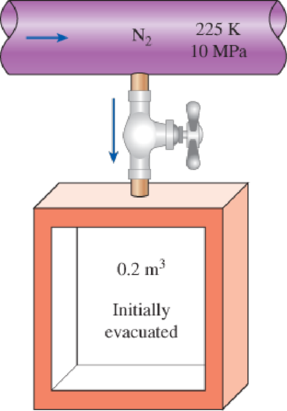
FIGURE P12–101
(a)
The final temperature in the tank by treating nitrogen as an ideal gas and compare the result to the actual value of
Answer to Problem 101RP
The final temperature in the tank by treating nitrogen as an ideal gas is
Explanation of Solution
Write the equation of mass balance.
Here, the inlet mass is
The change in mass of the system for the control volume is expressed as,
Here, the suffixes 1 and 2 indicates the initial and final states of the system.
Consider the given insulated tank as the control volume.
The valve is closed when the pressure in tank reaches to
Rewrite the Equation (I) as follows.
Write the energy balance equation.
Here, the heat transfer is
Since the tank is adiabatic, there is no heat transfer i.e.
The Equation (III) reduced as follows.
Substitute
Express the Equation (V) in molar basis.
Here, the molar mass of nitrogen is
Conclusion:
The inlet condition of the nitrogen is
While considering the nitrogen as the ideal gas, its enthalpy is solely depends on temperature.
Refer Table A-18, “Ideal-gas properties of nitrogen,
The molar enthalpy of nitrogen corresponding to the temperature of
Refer Equation (VI).
The final temperature of the nitrogen is expressed as follows.
Refer Table A-18, “Ideal-gas properties of nitrogen,
The final temperature
Thus, the final temperature in the tank by treating nitrogen as an ideal gas is
The percentage error with the actual temperature value of
The error associated is
(b)
The final temperature in the tank by using generalized departure charts.
Answer to Problem 101RP
The final temperature in the tank by using generalized departure charts is
Explanation of Solution
Refer Table A-1, “Molar mass, gas constant, and critical-point properties”.
The critical temperature and pressure of nitrogen gas is as follows.
The reduced pressure
At inlet:
Refer Figure A-29, “Generalized enthalpy departure chart”.
The enthalpy departure factor
Write formula for enthalpy departure factor
Here, the inlet molar enthalpy at ideal gas state is
Rearrange the Equation (I) to obtain
Write the formula for molar enthalpy at final state
Write the formula for molar internal energy at final state.
Here, the compressibility factor is
The universal gas constant
Conclusion:
Refer part (a) answer for
Substitute
Refer Equation (VI).
It is given that the actual final temperature of nitrogen is
Consider the exit temperature
The reduced pressure
Refer Figure A-29, “Generalized enthalpy departure chart”.
The enthalpy departure factor
Refer Figure A-15, “Nelson–Obert generalized compressibility chart”.
The compressibility factor
Refer Table A-18, “Ideal-gas properties of nitrogen,
The final molar enthalpy of nitrogen
Substitute
Substitute
Express interpolation formula to determine the final temperature
Substitute
Thus, the final temperature in the tank by using generalized departure charts is
The percentage error with the actual temperature value of
The error associated is
Want to see more full solutions like this?
Chapter 12 Solutions
Thermodynamics: An Engineering Approach ( 9th International Edition ) ISBN:9781260092684


- Question 1. Draw 3 teeth for the following pinion and gear respectively. The teeth should be drawn near the pressure line so that the teeth from the pinion should mesh those of the gear. Drawing scale (1:1). Either a precise hand drawing or CAD drawing is acceptable. Draw all the trajectories of the involute lines and the circles. Specification: 18tooth pinion and 30tooth gear. Diameter pitch=P=6 teeth /inch. Pressure angle:20°, 1/P for addendum (a) and 1.25/P for dedendum (b). For fillet, c=b-a.arrow_forward5. The figure shows a gear train. There is no friction at the bearings except for the gear tooth forces. The material of the milled gears is steel having a Brinell hardness of 170. The input shaft speed (n2) is 800 rpm. The face width and the contact angle for all gears are 1 in and 20° respectively. In this gear set, the endurance limit (Se) is 15 kpsi and nd (design factor) is 2. (a) Find the revolution speed of gear 5. (b) Determine whether each gear satisfies the design factor of 2.0 for bending fatigue. (c) Determine whether each gear satisfies the design factor of 2.0 for surface fatigue (contact stress). (d) According to the computation results of the questions (b) and (c), explain the possible failure mechanisms for each gear. N4=28 800rpm N₁=43 N5=34 N₂=14 P(diameteral pitch)=8 for all gears Coupled to 2.5hp motorarrow_forward1. The rotating steel shaft is simply supported by bearings at points of B and C, and is driven by a spur gear at D, which has a 6-in pitch diameter. The force F from the drive gear acts at a pressure angle of 20°. The shaft transmits a torque to point A of TA =3000 lbĘ in. The shaft is machined from steel with Sy=60kpsi and Sut=80 kpsi. (1) Draw a shear force diagram and a bending moment diagram by F. According to your analysis, where is the point of interest to evaluate the safety factor among A, B, C, and D? Describe the reason. (Hint: To find F, the torque Tд is generated by the tangential force of F (i.e. Ftangential-Fcos20°) When n=2.5, K=1.8, and K₁ =1.3, determine the diameter of the shaft based on (2) static analysis using DE theory (note that fatigue stress concentration factors need to be used for this question because the loading condition is fatigue) and (3) a fatigue analysis using modified Goodman. Note) A standard diameter is not required for the questions. 10 in Darrow_forward
- 3 N2=28 P(diametral pitch)=8 for all gears Coupled to 25 hp motor N3=34 Full depth spur gears with pressure angle=20° N₂=2000 rpm (1) Compute the circular pitch, the center-to-center distance, and base circle radii. (2) Draw the free body diagram of gear 3 and show all the forces and the torque. (3) In mounting gears, the center-to-center distance was reduced by 0.1 inch. Calculate the new values of center-to-center distance, pressure angle, base circle radii, and pitch circle diameters. (4)What is the new tangential and radial forces for gear 3? (5) Under the new center to center distance, is the contact ratio (mc) increasing or decreasing?arrow_forward2. A flat belt drive consists of two 4-ft diameter cast-iron pulleys spaced 16 ft apart. A power of 60 hp is transmitted by a pulley whose speed is 380 rev/min. Use a service factor (Ks) pf 1.1 and a design factor 1.0. The width of the polyamide A-3 belt is 6 in. Use CD=1. Answer the following questions. (1) What is the total length of the belt according to the given geometry? (2) Find the centrifugal force (Fc) applied to the belt. (3) What is the transmitted torque through the pulley system given 60hp? (4) Using the allowable tension, find the force (F₁) on the tight side. What is the tension at the loose side (F2) and the initial tension (F.)? (5) Using the forces, estimate the developed friction coefficient (f) (6) Based on the forces and the given rotational speed, rate the pulley set. In other words, what is the horse power that can be transmitted by the pulley system? (7) To reduce the applied tension on the tight side, the friction coefficient is increased to 0.75. Find out the…arrow_forwardThe tooth numbers for the gear train illustrated are N₂ = 24, N3 = 18, №4 = 30, №6 = 36, and N₁ = 54. Gear 7 is fixed. If shaft b is turned through 5 revolutions, how many turns will shaft a make? a 5 [6] barrow_forward
- Please do not use any AI tools to solve this question. I need a fully manual, step-by-step solution with clear explanations, as if it were done by a human tutor. No AI-generated responses, please.arrow_forwardPlease do not use any AI tools to solve this question. I need a fully manual, step-by-step solution with clear explanations, as if it were done by a human tutor. No AI-generated responses, please.arrow_forwardCE-112 please solve this problem step by step and give me the correct answerarrow_forward
 Principles of Heat Transfer (Activate Learning wi...Mechanical EngineeringISBN:9781305387102Author:Kreith, Frank; Manglik, Raj M.Publisher:Cengage Learning
 Refrigeration and Air Conditioning Technology (Mi...Mechanical EngineeringISBN:9781305578296Author:John Tomczyk, Eugene Silberstein, Bill Whitman, Bill JohnsonPublisher:Cengage Learning