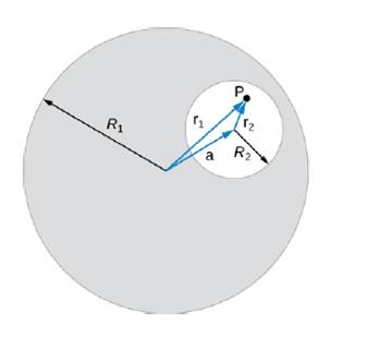
A long, straight, cylindrical conductor contains a cylindrical cavity whose axis is displaced by n from the axis of the conductor, as shown in the accompanying figure. The current density in the conductor is given by J → = J 0 k ^ , where J 0 is a constant and k ^ is along the axis of the conductor. Calculate the magnetic field at an arbitrary point P in the cavity by superimposing the field of a solid cylindrical conductor with radius R 1 and current density J → onto the field of a solid cylindrical conductor with radius R 2 and current density − J → . Then use the fact that the appropriate azimuthal unit vectors can be expressed as θ ^ 1 = k ^ × r ^ 1 and θ ^ 2 = k ^ × r ^ 2 to show that everywhere inside the cavity the magnetic field is given by the constant B = 1 2 μ 0 J 0 k × a , where a = r 1 − r 2 and r 1 = r 1 r ^ 1 is the position of P relative to the center of the conductor and r 2 = r 2 r ^ 2 is the position of P relative to the center of the cavity.
A long, straight, cylindrical conductor contains a cylindrical cavity whose axis is displaced by n from the axis of the conductor, as shown in the accompanying figure. The current density in the conductor is given by J → = J 0 k ^ , where J 0 is a constant and k ^ is along the axis of the conductor. Calculate the magnetic field at an arbitrary point P in the cavity by superimposing the field of a solid cylindrical conductor with radius R 1 and current density J → onto the field of a solid cylindrical conductor with radius R 2 and current density − J → . Then use the fact that the appropriate azimuthal unit vectors can be expressed as θ ^ 1 = k ^ × r ^ 1 and θ ^ 2 = k ^ × r ^ 2 to show that everywhere inside the cavity the magnetic field is given by the constant B = 1 2 μ 0 J 0 k × a , where a = r 1 − r 2 and r 1 = r 1 r ^ 1 is the position of P relative to the center of the conductor and r 2 = r 2 r ^ 2 is the position of P relative to the center of the cavity.
A long, straight, cylindrical conductor contains a cylindrical cavity whose axis is displaced by n from the axis of the conductor, as shown in the accompanying figure. The current density in the conductor is given by
J
→
=
J
0
k
^
, where
J
0
is a constant and
k
^
is along the
axis of the conductor. Calculate the magnetic field at an arbitrary point P in the cavity by superimposing the field of a solid cylindrical conductor with radius R1and current density
J
→
onto the field of a solid cylindrical conductor with radius R2and current density
−
J
→
. Then use the fact that the appropriate azimuthal unit vectors can be expressed as
θ
^
1
=
k
^
×
r
^
1
and
θ
^
2
=
k
^
×
r
^
2
to show that everywhere inside the cavity the magnetic field is given by the constant
B
=
1
2
μ
0
J
0
k
×
a
, where
a
=
r
1
−
r
2
and
r
1
=
r
1
r
^
1
is the position of P relative to the center of the conductor and
r
2
=
r
2
r
^
2
is the position of P relative to the center of the cavity.
For each of the actions depicted, determine the direction (right, left, or zero) of the current induced to flow through the resistor in the circuit containing the secondary coil. The coils are wrapped around a plastic core. Immediately after the switch is closed, as shown in the figure, (Figure 1) in which direction does the current flow through the resistor? If the switch is then opened, as shown in the figure, in which direction does the current flow through the resistor? I have the answers to the question, but would like to understand the logic behind the answers. Please show steps.
When violet light of wavelength 415 nm falls on a single slit, it creates a central diffraction peak that is 8.60
cm wide on a screen that is 2.80 m away.
Part A
How wide is the slit?
ΟΙ ΑΣΦ
?
D= 2.7.10-8
Submit Previous Answers Request Answer
× Incorrect; Try Again; 8 attempts remaining
m
Two complex values are z1=8 + 8i, z2=15 + 7 i. z1∗ and z2∗ are the complex conjugate values.
Any complex value can be expessed in the form of a+bi=reiθ. Find θ for (z1-z∗2)/z1+z2∗. Find r and θ for (z1−z2∗)z1z2∗ Please show all steps


 Principles of Physics: A Calculus-Based TextPhysicsISBN:9781133104261Author:Raymond A. Serway, John W. JewettPublisher:Cengage Learning
 Physics for Scientists and Engineers: Foundations...PhysicsISBN:9781133939146Author:Katz, Debora M.Publisher:Cengage Learning
 Physics for Scientists and EngineersPhysicsISBN:9781337553278Author:Raymond A. Serway, John W. JewettPublisher:Cengage Learning
 Physics for Scientists and Engineers with Modern ...PhysicsISBN:9781337553292Author:Raymond A. Serway, John W. JewettPublisher:Cengage Learning
 Glencoe Physics: Principles and Problems, Student...PhysicsISBN:9780078807213Author:Paul W. ZitzewitzPublisher:Glencoe/McGraw-Hill