
(a)
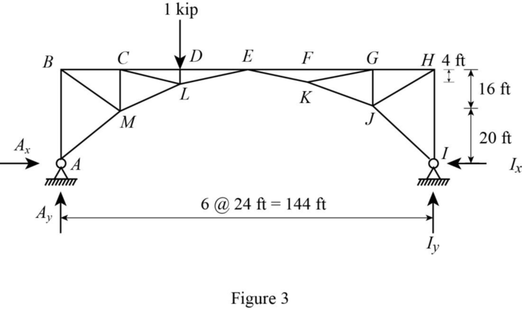
Draw the influence lines for the horizontal and vertical reactions at support A and the member forces in members BC, CM, and ML.
(a)
Explanation of Solution
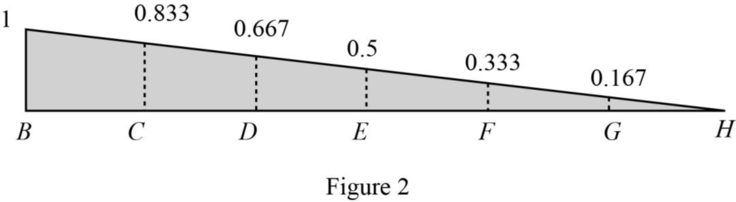
Influence line for the vertical reaction at A.
The influence line ordinate of
Apply 1 kip at D.
Find the vertical reaction at support A.
The reaction is determined by applying a 1-kip load at successive panel points.
Apply 1 kip load at C.
Draw the free body diagram as shown in Figure 1.

Refer Figure 1.
Consider moment equilibrium at I.
Thus, the influence line ordinate of vertical reaction at A is 0.667.
Similarly find the influence line ordinate of
| Points | x (ft) | Influence line ordinate of |
| B | 0 | 1 |
| C | 24 | 0.833 |
| D | 48 | 0.667 |
| E | 72 | 0.5 |
| F | 96 | 0.333 |
| G | 120 | 0.167 |
| H | 144 | 0 |
Draw the influence line ordinate of
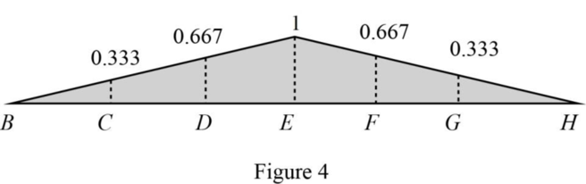
Influence line for the horizontal reaction at A.
The influence line ordinate of
Apply 1 kip at D.
Find the horizontal reaction at support A.
The reaction is determined by applying a 1-kip load at successive panel points.
Apply 1 kip load at C.
Draw the free body diagram as shown in Figure 3.
Refer Figure 4.
Consider moment equilibrium at E.
Thus, the influence line ordinate of horizontal reaction at A is 0.667.
Similarly find the influence line ordinate of
| Points | x (ft) | Influence line ordinate of |
| B | 0 | 0 |
| C | 24 | 0.333 |
| D | 48 | 0.667 |
| E | 72 | 1 |
| F | 96 | 0.667 |
| G | 120 | 0.333 |
| H | 144 | 00 |
Draw the influence line ordinate of
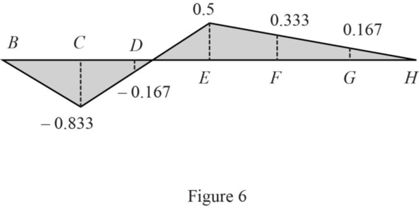
Influence line for the force in member BC.
Find the force
The influence line ordinate of
Apply 1 kip at C and consider a section passes through members BC, CM, and ML.
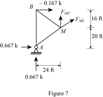
Sketch the free body diagram of the section as in Figure 5.
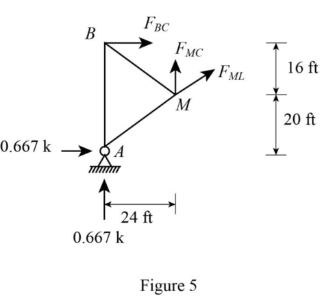
Refer Figure 5.
Find the member force BC.
Consider moment equilibrium at M.
Thus, the influence line ordinate of member force BC at D is ‑0.167.
Similarly find the influence line ordinate of
| Points | x (ft) | Influence line ordinate of |
| B | 0 | 0 |
| C | 24 | ‑0.833 |
| D | 48 | ‑0.167 |
| E | 72 | 0.5 |
| F | 96 | 0.333 |
| G | 120 | 0.167 |
| H | 144 | 0 |
Draw the influence line ordinate of
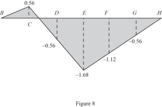
Influence line for the force in member ML.
Find the force
The influence line ordinate of
Apply 1 kip at C and consider a section passes through members BC, CM, and ML.
Sketch the free body diagram of the section as in Figure 7.
Refer Figure 7.
The slope of member ML is 24 ft horizontal and 12 ft vertical.
Find the member force ML.
Consider horizontal equilibrium equation.
Thus, the influence line ordinate of member force ML at D is ‑0.56.
Similarly find the influence line ordinate of
| Points | x (ft) | Influence line ordinate of |
| B | 0 | 0 |
| C | 24 | 0.56 |
| D | 48 | ‑0.56 |
| E | 72 | ‑1.68 |
| F | 96 | ‑1.12 |
| G | 120 | ‑0.56 |
| H | 144 | 0 |
Draw the influence line ordinate of
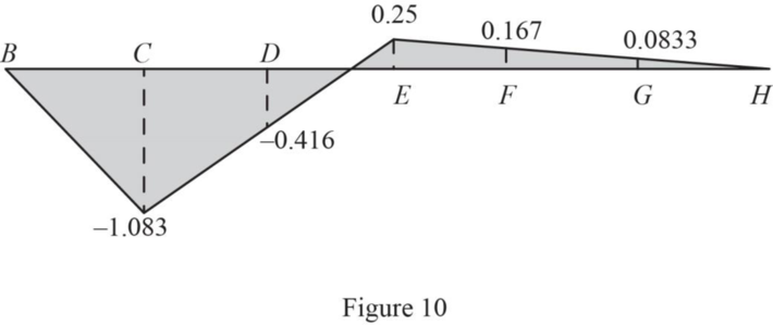
Influence line for the force in member CM.
Find the force
The influence line ordinate of
Apply 1 kip at C and consider a section passes through members BC, CM, and ML.
Sketch the free body diagram of the section as in Figure 9.
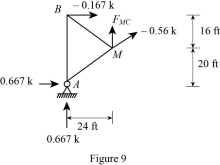
Refer Figure 9.
The slope of member ML is 24 ft horizontal and 12 ft vertical.
Find the member force CM.
Consider vertical equilibrium equation.
Thus, the influence line ordinate of member force CM at D is ‑0.416.
Similarly find the influence line ordinate of
| Points | x (ft) | Influence line ordinate of |
| B | 0 | 0 |
| C | 24 | ‑1.083 |
| D | 48 | ‑0.416 |
| E | 72 | 0.25 |
| F | 96 | 0.167 |
| G | 120 | 0.083 |
| H | 144 | 0 |
Draw the influence line ordinate of
(b)
Find the forces (compression and tension) in bars CM and ML produced by the dead load.
(b)
Answer to Problem 40P
The dead load force in member CM is
The dead load force in member ML is
Explanation of Solution
Given Information:
The uniform dead load,
Calculation:
Refer Figure 11.
Sketch the influence line diagram of member CM as in Figure 11.
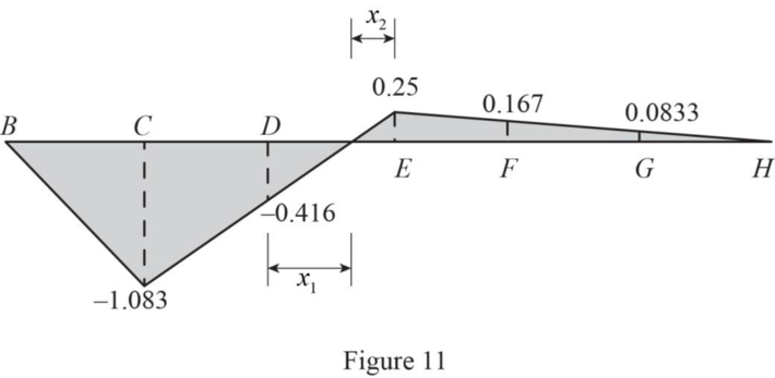
Refer Figure 11.
Find the length
Find the length
Refer Figure 11.
Find the dead load force in member CM using the equation.
Therefore, the dead load force in member CM is
Refer Figure 9.
Sketch the influence line diagram of member ML as in Figure 12.
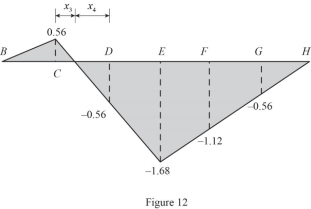
Refer Figure 12.
Find the length
Find the length
Refer Figure 11.
Find the dead load force in member CM using the equation.
Therefore, the dead load force in member ML is
(c)
Find the forces (compression and tension) in bars CM due to live load.
(c)
Answer to Problem 40P
The maximum compression force in member CM due to live load is
The maximum tension force in member CM due to live load is
Explanation of Solution
Given Information:
The uniform live load,
The concentrated live load, P is 20 k.
Calculation:
Refer Figure 11.
Sketch the influence line diagram of member CM as in Figure 13.
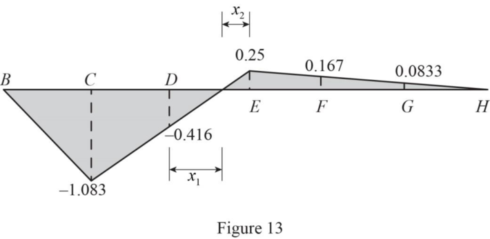
Refer Figure 13.
Find the maximum compression force in member CM using the equation.
Therefore, the maximum compression force in member CM due to live load is
Find the maximum tension force in member CM using the equation.
Therefore, the maximum tension force in member CM due to live load is
Want to see more full solutions like this?
Chapter 12 Solutions
Fundamentals Of Structural Analysis:

- I need detailed help solving this exercise from homework of Engineering Mathematics II.I do not really understand how to do, please do it step by step, not that long but clear. Thank you!P.S.: Please do not use AI, thanks!arrow_forwardI need solution by handarrow_forwardQ2: For the activities shown in the table below, it is required to reduce the total duration of the project four days by using crash program and network diagram, If you knew that indirect costs is 150 S/day and the delay fine is 100 $/day after the 14th day. Find new cost after crashing the project four days? Activity Preceding Normal Program Crash Program activity Duration (days) Direct Cost (S) Duration (days) Direct Cost (S) A 5 600 3 950 B - 4 200 3 500 C A 5 300 4 500 D A 2 600 1 615 E B 6 900 5 1025 800 3 F C 4 700 450 G D 4 400 3 700 3 700 1400 3 H E 2 600 I F,G,H 4 5000 Σ (40 px) good luck)arrow_forward
- I need detailed help solving this exercise from homework of Engineering Mathematics II.I do not really understand how to do, please do it step by step, not that long but clear. Thank you!P.S.: Please do not use AI, thanks!arrow_forwardDetermine the stiffness matrix of the frame as shown in Fig. 4. Nodes 1 and 3 are fixed supports. Assume I = 300(10^6) mm4, A = 10(10^3) mm2, E = 200 GPa for each member. Indicate the degrees-of freedom in all the stiffness matrices. Use the values of L3=2.5m, L4=4.5m, w=12kN/m and P=10kN. Please show all working and explain how the code numbers for global matrix are determined in detail.arrow_forwardI need detailed help solving this exercise from homework of Engineering Mathematics II.I do not really understand how to do, please do it step by step, not that long but clear. Thank you!P.S.: Please do not use AI, thanks!arrow_forward
- I need detailed help solving this exercise from homework of Engineering Mathematics II.I do not really understand how to do, please do it step by step, not that long but clear. Thank you!P.S.: Please do not use AI, thanks!arrow_forwardConsider the cross-section shown below. Assume the cross-section is subjected to an external axial force of 300 kN applied at the origin of the reference system shown (the origin is located at mid-height of the section). Note that the flanges have different thicknesses. Assume linear-elastic material properties and the section to be made of steel with elastic modulus E = 200 GPa. 110 4y 14 70 10 X 96 70 30 110 Notes: All dimensions in mm Sketch not to scale (i) Determine the strains and stresses induced in the cross-section by applying the cross-sectional analysis presented in the lecture notes. Provide all steps of your numerical calculations. (ii) Sketch the strain and stresses diagram based on the values calculated at point (i).arrow_forwardConsider the building floor layouts illustrated below. These are referred to as Floor Layout A and Floor Layout B. Assume the floor to be built with composite steel-concrete construction (i.e. it is a composite steel-concrete floor). concrete core typical column Floor Layout A concrete core perimeter of the building floor perimeter of the building floor Floor Layout B (i) Provide two qualitative floor layouts for the primary and secondary beams for the Floor Layout A (Floor Layout A is shown above). Make sure to clearly draw the 2 floor layouts highlighting primary and secondary beams. Comment on the advantages and disadvantages of the two floor layouts with respect to one another. (ii) Consider Floor Layout B (Floor Layout B is shown above) and sketch one qualitative floor layout in which you provide qualitative locations of the columns, primary beams and secondary beams. Comment on the benefits of your selection of the positions of the beams and columns. Feel free to introduce any…arrow_forward
- Consider the two composite columns shown below and denoted as columns 1 and 2. These columns have same gross area but differ in the geometries of the steel and concrete components. In particular, the square steel hollow section in section A-A (for column 1) has thickness of t, while the square steel hollow section in section B-B (for column 2) has thickness of 2t. a t t Column 1 steel steel concrete concrete B B Column 2 2t 2t 2t 2t a a Section A-A (for column 1) a Section B-B (for column 2) Assume that these columns are subjected to the same sustained load Po applied at time to and maintained constant afterwards (see time axis below). РА Ро 0 time Provide a qualitative description of the variation over time due to creep effects (do not consider shrinkage effects in this question) of the following variables for each of the two columns considered (i.e. columns 1 and 2): 1) deformations in the concrete 2) deformations in the steel 3) stresses in the concrete 4) stresses in the steel For…arrow_forwardFor the truss shown in Fig 2, determine the nodal displacement and member forces for all elements of the truss. Assume for each member A = 0.0015 m2 and E = 200 GPa please show all working, relevant FBD's and use ID's indicated in the diagram. Note: the truss has a vertical measurement of 2m and a horizontal mesurement of 2marrow_forwardα t Αν 'A B 'B Column 1 Column 2 t t α Section A-A (for column 1) steel steel concrete concrete 2t 2t 2t 2t a Section B-B (for column 2)arrow_forward

 Structural Analysis (10th Edition)Civil EngineeringISBN:9780134610672Author:Russell C. HibbelerPublisher:PEARSON
 Principles of Foundation Engineering (MindTap Cou...Civil EngineeringISBN:9781337705028Author:Braja M. Das, Nagaratnam SivakuganPublisher:Cengage Learning
 Fundamentals of Structural AnalysisCivil EngineeringISBN:9780073398006Author:Kenneth M. Leet Emeritus, Chia-Ming Uang, Joel LanningPublisher:McGraw-Hill Education
 Traffic and Highway EngineeringCivil EngineeringISBN:9781305156241Author:Garber, Nicholas J.Publisher:Cengage Learning