
Videos
An inductor is an electrical device that can store energy in the form of a magnetic field. In the simplest form, an inductor is a cylindrical coil of wire, and its inductance (L), measured in henrys [H), can be calculated by
Where
µ0 =.permeability of free space=4π × 10-7 [newtons per ampere squared, N/ A2]
n = number of turns of wire [dimensionless]
A = cross-sectional area of coil [square meters, m2]
l = length of coil [meters, m]
L = inductance [henrys, H] = [J /A2]
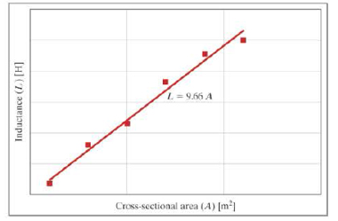 Several inductors were fabricated with the same number of turns of wire (n) and the same length (ℓ), but with different diameters, thus different cross-sectional areas (A). The inductances were measured and plotted as a function of cross-sectional area, and a mathematical model was developed to describe the relationship, as shown on the following graph.
- a. What are the units of the slope (9.66)?
- b. For an inductor fabricated as described above, what is its diameter if its inductance is 0.4 henrys?
Give your answer in centimeters.
- c. If the length of the coil (ℓ) equals 0.2 meter, how many turns of wire (n) are in the inductor?
Want to see the full answer?
Check out a sample textbook solution
Chapter 12 Solutions
Thinking Like an Engineer: An Active Learning Approach (4th Edition)


- Correct answer and complete fbd only. I will upvote. 6: The shaft carries a total torque T0 that is uniformly distributedover its length L. Determine the angle of twist (degrees) of the shaft in termsif T0 = 1.2 kN-m, L = 2 m, G = 80 GPa, and diameter = 120 mm.arrow_forward2. Calculate the force in all members of the trusses shown using the method of joints. A 5525 lb C 3500 lb BY 14'-0" D 10'- 0" 6250 lb 10'- 0" Earrow_forwardCorrect answer and complete fbd only. I will upvote. 8: The steel rod fits loosely inside the aluminum sleeve. Both components are attached to a rigid wall at A andjoined together by a pin at B. Because of a slight misalignmentof the pre-drilled holes, the torque T0 = 750 N-m was appliedto the steel rod before the pin could be inserted into theholes. Determine the torque (N-m) in each component afterT0 was removed. Use G = 80 GPa for steel and G = 28 GPa foraluminumarrow_forward
- Correct answer and complete fbd only. I will upvote. 9: The two steel shafts, each with one end builtinto a rigid support, have flanges attached to their freeends. The flanges are to be bolted together. However,initially there is a 6⁰ mismatch in the location of the boltholes as shown in the figure. Determine the maximumshear stress(ksi) in each shaft after the flanges have beenbolted together. The shear modulus of elasticity for steelis 12 x 106 psi. Neglect deformations of the bolts and theflanges.arrow_forwardCorrect answer and complete fbd only. I will upvote. The tapered, wrought iron shaft carriesthe torque T = 2000 lb-in at its free end. Determine theangle of twist (degrees) of the shaft. Use G = 10 x 106psi for wrought ironarrow_forwardCorrect answer and complete fbd only. I will upvote. The compound shaft, consisting of steel and aluminumsegments, carries the two torques shown in the figure. Determine themaximum permissible value of T subject to the following designconditions: τst ≤ 83 MPa, τal ≤ 55 MPa, and θ ≤ 6⁰ (θ is the angle ofrotation of the free end). Use G =83 GPa for steel and G = 28 GPa foraluminum.arrow_forward
- The solid compound shaft, made of threedifferent materials, carries the two torques shown. Theshear moduli are 28 GPa for aluminum, 83 GPa for steel,and 35 GPa for bronze.1. Calculate the maximum shear stress (MPa) in eachmaterial.2. Find the angle of rotation (degrees) of the free endof the shaft.arrow_forwardCorrect answer only please. I will upvote. The velocity of a particle moves along the x-axis and is given by the equation ds/dt = 40 - 3t^2 m/s. Calculate the acceleration at time t=2 s and t=4 s. Calculate also the total displacement at the given interval. Assume at t=0 s=5m.Write the solution using pen and draw the graph if needed.arrow_forwardI want the steps of operation of the circuit, clearly in detail. Please. LV1arrow_forward
- Complet the solution: Vavg Ti Te Ts Qhexp Nuexp htheo Re Nutheo Error (m/s) (°C) (°C) (°C) (W) 2.11 18.8 21.3 45.8 2.61 18.5 20.8 46.3 Heat transfer Given data: a= 10 cm. L= 10 cm. b= 20 cm. H=40cm. ⚫ a = 10, cm: This could represent the width of the duct. ⚫b=20, cm: This might be the height of the duct. ⚫L = 10, cm: This usually stands for the length of the duct in the direction of flow. ⚫H=40, cm: This could indicate the height of some component or another duct-related dimension, but the exact meaning depends on the experiment's context.arrow_forwardplease explain each step and include drawings on the phase diagram. thanksarrow_forwardWrite clearly which points correspond to concentration of solute in front of alpha, concentration of solute in front of beta, amount of solid in the liquid in front of alpha/beta, lowest possible energy (tangent), as well as any other important information. Thank youarrow_forward
 Elements Of ElectromagneticsMechanical EngineeringISBN:9780190698614Author:Sadiku, Matthew N. O.Publisher:Oxford University Press
 Mechanics of Materials (10th Edition)Mechanical EngineeringISBN:9780134319650Author:Russell C. HibbelerPublisher:PEARSON
 Thermodynamics: An Engineering ApproachMechanical EngineeringISBN:9781259822674Author:Yunus A. Cengel Dr., Michael A. BolesPublisher:McGraw-Hill Education
 Control Systems EngineeringMechanical EngineeringISBN:9781118170519Author:Norman S. NisePublisher:WILEY
 Mechanics of Materials (MindTap Course List)Mechanical EngineeringISBN:9781337093347Author:Barry J. Goodno, James M. GerePublisher:Cengage Learning
 Engineering Mechanics: StaticsMechanical EngineeringISBN:9781118807330Author:James L. Meriam, L. G. Kraige, J. N. BoltonPublisher:WILEY