
Videos
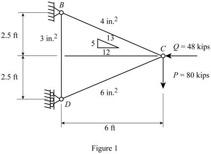
11.101 and 11.102 Each member of the truss shown is made of steel and has the cross-sectional area shown. Using E = 29 × 106 psi, determine the deflection indicated.
11.101 Vertical deflection of joint C.
11.102 Horizontal deflection of joint C.
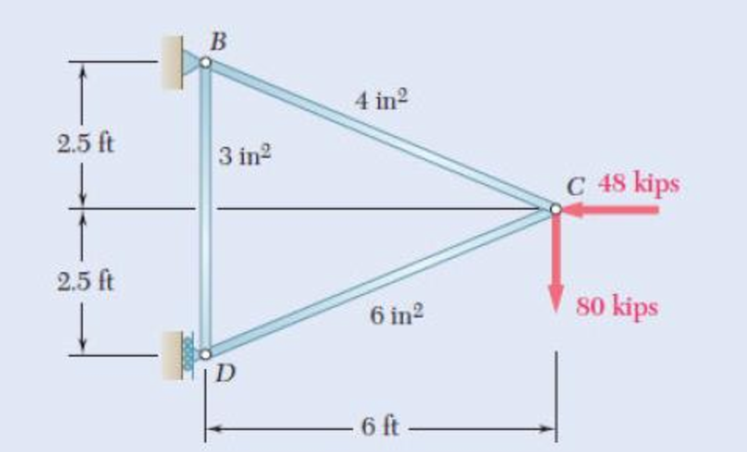
Fig. P11.101 and P11.102
Calculate the horizontal deflection of joint C
Answer to Problem 102P
The horizontal deflection of joint C
Explanation of Solution
Given information:
The Young’s modulus of the steel (E) is
The area of the member BC
The area of the member BD
The area of the member CD
The vertical load act at the joint C (P) is
The horizontal load act at the joint C (G) is
The length of the member BD
The length of the member (L) is
Calculation:
Show the free body diagram of the truss members as in Figure 1.
Refer to Figure 1.
The length of the member BC
The length of the member CD
The length of the member BD
Show the diagram of the joint C as in Figure 2.
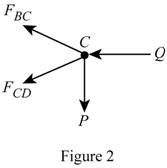
Here,
Refer to Figure 2.
Calculate the horizontal forces by applying the equation of equilibrium:
Sum of horizontal forces is equal to 0.
Calculate the vertical forces by applying the equation of equilibrium:
Sum of vertical forces is equal to 0.
Calculate the force act at the member CD
Substitute
Calculate the force act at the member BC
Substitute
Show the diagram of the joint D as in Figure 3.
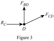
Here,
Refer to Figure 3.
Calculate the vertical forces by applying the equation of equilibrium:
Sum of vertical forces is equal to 0.
Substitute
Partial differentiate the force act at the member BC
Calculate the deflection of the member BC
Substitute
Partial differentiate the force act at the member CD
Calculate the deflection of the member CD
Substitute
Partial differentiate the force act at the member BD
Calculate the strain energy of the member BD
Substitute
Calculate the vertical deflection of joint C
Substitute
Substitute
Hence the horizontal deflection of joint C
Want to see more full solutions like this?
Chapter 11 Solutions
EBK MECHANICS OF MATERIALS


- The shaft shown in the sketch is subjected to tensile torsional and bending loads Determine the principal stresses at the location of stress concentration ✓ D=45MR F=3MM 1000-M 1000N チ d=30mm 500N 150 мм MM- 120 MA-arrow_forwardcalculate moment of inertia of this tapered beam structurearrow_forwardThe system shown below is in statics equilibrium. Cable OB lies in the xy plane and makes a 30° angle with the positive x-axis. Cable OA lies along the negative y-axis. If the weight of the load being supported is 100 lb, determine the magnitude of the forces in all four cables: OA, OB, OC, and OD.arrow_forward
- This is a mechanics/statics problem involving finding internal reactions, V(x) and M(x). Please refer to image for details. I'm not sure about where to take cuts and how to formulate the equations as a function of x. For my support Reactions I got Ay = 1008.33 lb, By = 1416.67 lb and Cy = 175 lb. and for the first cut V(x) = 1008.33 -250(x) and M(x) = 1008.33x - 125x^2. I'm struggling with the equations for the 2nd and 3rd cut.arrow_forwardAs shown in the figure below, a ring is used to suspend a load and is supported by Cable OA and Spring OB. Given that the tension in Cable OA is 400 N, what is the weight of the load being supported? Assume the system is in static equilibrium.arrow_forward4. (a) State the conditions that must be met to ensure dynamic balance is achieved for long rotors. (b) A rotor carries three out-of-balance discs in planes A, B and C as shown in Figure 4. The out-of- balance mass x radius products of the rotor discs are tabulated in Table 4. The shaft is to be dynamically balanced by adding balancing masses in planes P and Q, spaced along the shaft at a distance da = 800 mm. Determine the magnitude mara and angular position of the balancing mass x radius product that must be added to plane Q. MBB Ов θε mdc Мага End View on Plane P P MBB MATA dA dB dc do Figure 4 moc Table 4 MATA = 0.6 kg mm 6A = 0° d₁ = 200 mm mers = 0.2 kg mm 6g = 45° dB = 400 mm mcrc = 0.4 kg mm Bc=240° dc = 600 mm Ans. (b) = 110.5°, moro = 0.2 kg mmarrow_forward
- Need help in adding demensioning am am so confusedarrow_forwardComplete the following activity. Save as .pdf and upload to the assignment to the dropbox. 口 Use the general dimensioning symbols to correctly specify the following requirements on the drawing above.arrow_forwardplease solve and show workarrow_forward
- Water is boiling in a 25 cm diameter aluminum pan (k=237 W/mK) at 95 degrees C. Heat is transferred steadily to the boiling water in the pan through its .5 cm thick flat bottom at a rate of 800 W. if the inner surface temp of the bottom of the pan is 108 degrees C determine the boiling heat transfer coefficent on the inner surface of the pan and the outer surface temp of the bottom of the pan.arrow_forwardplease solve and show workarrow_forwardplease solve and show workarrow_forward
 Elements Of ElectromagneticsMechanical EngineeringISBN:9780190698614Author:Sadiku, Matthew N. O.Publisher:Oxford University Press
 Mechanics of Materials (10th Edition)Mechanical EngineeringISBN:9780134319650Author:Russell C. HibbelerPublisher:PEARSON
 Thermodynamics: An Engineering ApproachMechanical EngineeringISBN:9781259822674Author:Yunus A. Cengel Dr., Michael A. BolesPublisher:McGraw-Hill Education
 Control Systems EngineeringMechanical EngineeringISBN:9781118170519Author:Norman S. NisePublisher:WILEY
 Mechanics of Materials (MindTap Course List)Mechanical EngineeringISBN:9781337093347Author:Barry J. Goodno, James M. GerePublisher:Cengage Learning
 Engineering Mechanics: StaticsMechanical EngineeringISBN:9781118807330Author:James L. Meriam, L. G. Kraige, J. N. BoltonPublisher:WILEY