
EBK MECHANICS OF MATERIALS
7th Edition
ISBN: 9780100257061
Author: BEER
Publisher: YUZU
expand_more
expand_more
format_list_bulleted
Concept explainers
Videos
Textbook Question
Chapter 11.5, Problem 75P
Each member of the truss shown is made of steel and has a cross-sectional area of 5 in2. Using E = 29 × 106 psi, determine the vertical deflection of point C caused by the 15-kip load.
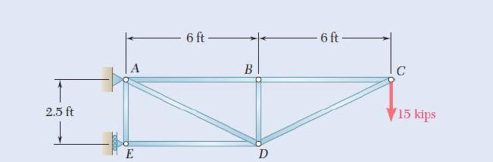
Fig. P11.75
Expert Solution & Answer
Want to see the full answer?
Check out a sample textbook solution
Students have asked these similar questions
(read image)
(read image)
(read image)
Chapter 11 Solutions
EBK MECHANICS OF MATERIALS
Ch. 11.3 - Determine the modulus of resilience for each of...Ch. 11.3 - Determine the modulus of resilience for each of...Ch. 11.3 - Determine the modulus of resilience for each of...Ch. 11.3 - Determine the modulus of resilience for each of...Ch. 11.3 - The stress-strain diagram shown has been drawn...Ch. 11.3 - The stress-strain diagram shown has been drawn...Ch. 11.3 - Prob. 7PCh. 11.3 - Prob. 8PCh. 11.3 - Using E = 29 106 psi, determine (a) the strain...Ch. 11.3 - Using E = 200 GPa, determine (a) the strain energy...
Ch. 11.3 - A 30-in. length of aluminum pipe of...Ch. 11.3 - A single 6-mm-diameter steel pin B is used to...Ch. 11.3 - Prob. 13PCh. 11.3 - Prob. 14PCh. 11.3 - The assembly ABC is made of a steel for which E =...Ch. 11.3 - Show by integration that the strain energy of the...Ch. 11.3 - Prob. 17PCh. 11.3 - Prob. 18PCh. 11.3 - Prob. 19PCh. 11.3 - 11.18 through 11.21 In the truss shown, all...Ch. 11.3 - Prob. 21PCh. 11.3 - Each member of the truss shown is made of aluminum...Ch. 11.3 - Each member of the truss shown is made of aluminum...Ch. 11.3 - 11.24 through 11.27 Taking into account only the...Ch. 11.3 - Prob. 25PCh. 11.3 - 11.24 through 11.27 Taking into account only the...Ch. 11.3 - 11.24 through 11.27 Taking into account only the...Ch. 11.3 - Prob. 28PCh. 11.3 - Prob. 29PCh. 11.3 - Prob. 30PCh. 11.3 - 11.30 and 11.31 Using E = 200 GPa, determine the...Ch. 11.3 - Assuming that the prismatic beam AB has a...Ch. 11.3 - Prob. 33PCh. 11.3 - The design specifications for the steel shaft AB...Ch. 11.3 - Show by integration that the strain energy in the...Ch. 11.3 - The state of stress shown occurs in a machine...Ch. 11.3 - Prob. 37PCh. 11.3 - The state of stress shown occurs in a machine...Ch. 11.3 - Prob. 39PCh. 11.3 - Prob. 40PCh. 11.3 - Prob. 41PCh. 11.5 - A 5-kg collar D moves along the uniform rod AB and...Ch. 11.5 - The 18-lb cylindrical block E has a horizontal...Ch. 11.5 - The cylindrical block E has a speed v0 =16 ft/s...Ch. 11.5 - Prob. 45PCh. 11.5 - Prob. 46PCh. 11.5 - The 48-kg collar G is released from rest in the...Ch. 11.5 - Prob. 48PCh. 11.5 - Prob. 49PCh. 11.5 - Prob. 50PCh. 11.5 - Prob. 51PCh. 11.5 - The 2-kg block D is dropped from the position...Ch. 11.5 - The 10-kg block D is dropped from a height h = 450...Ch. 11.5 - Prob. 54PCh. 11.5 - A 160-lb diver jumps from a height of 20 in. onto...Ch. 11.5 - Prob. 56PCh. 11.5 - A block of weight W is dropped from a height h...Ch. 11.5 - 11.58 and 11.59 Using the method of work and...Ch. 11.5 - 11.58 and 11.59 Using the method of work and...Ch. 11.5 - 11.60 and 11.61 Using the method of work and...Ch. 11.5 - 11.60 and 11.61 Using the method of work and...Ch. 11.5 - 11.62 and 11.63 Using the method of work and...Ch. 11.5 - 11.62 and 11.63 Using the method of work and...Ch. 11.5 - Using the method of work and energy, determine the...Ch. 11.5 - Using the method of work and energy, determine the...Ch. 11.5 - The 20-mm diameter steel rod BC is attached to the...Ch. 11.5 - Torques of the same magnitude T are applied to the...Ch. 11.5 - Prob. 68PCh. 11.5 - The 20-mm-diameter steel rod CD is welded to the...Ch. 11.5 - The thin-walled hollow cylindrical member AB has a...Ch. 11.5 - 11.71 and 11.72 Each member of the truss shown has...Ch. 11.5 - 11.71 and 11.72 Each member of the truss shown has...Ch. 11.5 - Each member of the truss shown is made of steel...Ch. 11.5 - Each member of the truss shown is made of steel....Ch. 11.5 - Each member of the truss shown is made of steel...Ch. 11.5 - The steel rod BC has a 24-mm diameter and the...Ch. 11.9 - 11.77 and 11.78 Using the information in Appendix...Ch. 11.9 - 11.77 and 11.78 Using the information in Appendix...Ch. 11.9 - 11.79 through 11.82 For the beam and loading...Ch. 11.9 - 11.79 through 11.82 For the beam and loading...Ch. 11.9 - 11.79 through 11.82 For the beam and loading...Ch. 11.9 - 11.79 through 11.82 For the beam and loading...Ch. 11.9 - 11.83 through 11.85 For the prismatic beam shown,...Ch. 11.9 - 11.83 through 11.85 For the prismatic beam shown,...Ch. 11.9 - 11.83 through 11.85 For the prismatic beam shown,...Ch. 11.9 - 11.86 through 11.88 For the prismatic beam shown,...Ch. 11.9 - 11.86 through 11.88 For the prismatic beam shown,...Ch. 11.9 - 11.86 through 11.88 For the prismatic beam shown,...Ch. 11.9 - For the prismatic beam shown, determine the slope...Ch. 11.9 - For the prismatic beam shown, determine the slope...Ch. 11.9 - For the beam and loading shown, determine the...Ch. 11.9 - For the beam and loading shown, determine the...Ch. 11.9 - 11.93 and 11.94 For the beam and loading shown,...Ch. 11.9 - 11.93 and 11.94 For the beam and loading shown,...Ch. 11.9 - For the beam and loading shown, determine the...Ch. 11.9 - For the beam and loading shown, determine the...Ch. 11.9 - Prob. 97PCh. 11.9 - For the beam and loading shown, determine the...Ch. 11.9 - 11.99 and 11.100 For the truss and loading shown,...Ch. 11.9 - 11.99 and 11.100 For the truss and loading shown,...Ch. 11.9 - 11.101 and 11.102 Each member of the truss shown...Ch. 11.9 - 11.101 and 11.102 Each member of the truss shown...Ch. 11.9 - 11.103 and 11.104 Each member of the truss shown...Ch. 11.9 - 11.103 and 11 104 Each member of the truss shown...Ch. 11.9 - A uniform rod of flexural rigidity EI is bent and...Ch. 11.9 - For the uniform rod and loading shown and using...Ch. 11.9 - For the beam and loading shown and using...Ch. 11.9 - Two rods AB and BC of the same flexural rigidity...Ch. 11.9 - Three rods, each of the same flexural rigidity EI,...Ch. 11.9 - Three rods, each of the same flexural rigidity EI,...Ch. 11.9 - 11.111 through 11.115 Determine the reaction at...Ch. 11.9 - 11.111 through 11.115 Determine the reaction at...Ch. 11.9 - 11.111 through 11.115 Determine the reaction at...Ch. 11.9 - 11.111 through 11.115 Determine the reaction at...Ch. 11.9 - 11.111 through 11.115 Determine the reaction at...Ch. 11.9 - For the uniform beam and loading shown, determine...Ch. 11.9 - 11.117 through 11.120 Three members of the same...Ch. 11.9 - 11.117 through 11.120 Three members of the same...Ch. 11.9 - 11.117 through 11.120 Three members of the same...Ch. 11.9 - 11.117 through 11.120 Three members of the same...Ch. 11.9 - 11.121 and 11.122 Knowing that the eight members...Ch. 11.9 - 11.121 and 11.122 Knowing that the eight members...Ch. 11 - Rod AB is made of a steel for which the yield...Ch. 11 - Each member of the truss shown is made of steel...Ch. 11 - The ship at A has just started to drill for oil on...Ch. 11 - Collar D is released from rest in the position...Ch. 11 - Each member of the truss shown is made of steel...Ch. 11 - A block of weight W is placed in contact with a...Ch. 11 - Two solid steel shafts are connected by the gears...Ch. 11 - A 160-lb diver jumps from a height of 20 in. onto...Ch. 11 - For the prismatic beam shown, determine the slope...Ch. 11 - A disk of radius a has been welded to end B of the...Ch. 11 - A uniform rod of flexural rigidity EI is bent and...Ch. 11 - The steel bar ABC has a square cross section of...
Knowledge Booster


Learn more about
Need a deep-dive on the concept behind this application? Look no further. Learn more about this topic, mechanical-engineering and related others by exploring similar questions and additional content below.Similar questions
- (read me)arrow_forward(read image)arrow_forwardQu. 13 What are the indices for the Direction 2 indicated by vector in the following sketch? Qu. 14 Determine the indices for the direction A and B shown in the following cubic unit cell. please show all work step by step from material engineeringarrow_forward
- The thin-walled open cross section shown is transmitting torque 7. The angle of twist ₁ per unit length of each leg can be determined separately using the equation 01 = 3Ti GLIC 3 where G is the shear modulus, ₁ is the angle of twist per unit length, T is torque, and L is the length of the median line. In this case, i = 1, 2, 3, and T; represents the torque in leg i. Assuming that the angle of twist per unit length for each leg is the same, show that T= Lic³ and Tmaz = G01 Cmax Consider a steel section with Tallow = 12.40 kpsi. C1 2 mm L1 20 mm C2 3 mm L2 30 mm C3 2 mm L3 25 mm Determine the torque transmitted by each leg and the torque transmitted by the entire section. The torque transmitted by the first leg is | N-m. The torque transmitted by the second leg is N-m. The torque transmitted by the third leg is N-m. The torque transmitted by the entire section is N-m.arrow_forwardPlease help, make sure it's to box out and make it clear what answers go where...arrow_forwardThe cylinder floats in the water and oil to the level shown. Determine the weight of the cylinder. (rho)o=910 kg/m^3arrow_forward
- A triangular distributed load of max intensity w acts on beam AB. The beam is supported by a pin at A and member CD, which is connected by pins at C and D respectively. Determine the largest load intensity, Wmax, that can be applied if the pin at D can support a maximum force of 18000 N. Also determine the reactions at A and C and express each answer in Cartesian components. Assume the masses of both beam and member ✓ are negligible. Dwas шал = A BY NC SA 2016 Eric Davishahl C D -a- Ур -b- X B W Values for dimensions on the figure are given in the following table. Note the figure may not be to scale. Variable Value a 6.6 m b 11.88 m C 4.29 m The maximum load intensity is = wmax N/m. The reaction at A is A = The reaction at C is = i+ Ĵ N. ĴN. 12 i+arrow_forwardThe beam is supported by a pin at B and a roller at C and is subjected to the loading shown with w =110 lb/ft, and F 205 lb. a.) If M = 2,590 ft-lb, determine the support reactions at B and C. Report your answers in both Cartesian components. b.) Determine the largest magnitude of the applied couple M for which the beam is still properly supported in equilibrium with the pin and roller as shown. 2013 Michael Swanbom CC BY NC SA M ру W B⚫ C F ka b Values for dimensions on the figure are given in the following table. Note the figure may not be to scale. Variable Value a 3.2 ft b 6.4 ft C 3 ft a.) The reaction at B is B = The reaction at C is C = ĵ lb. i+ Ĵ lb. b.) The largest couple that can be applied is M ft-lb. == i+arrow_forwardThe beam ABC has a mass of 79.0 kg and is supported by the rope BDC that runs through the frictionless pulley at D . The winch at C has a mass of 36.5 kg. The tension in the rope acts on the beam at points B and C and counteracts the moments due to the beam's weight (acting vertically at the midpoint of its length) and the weight of the winch (acting vertically at point C) such that the resultant moment about point A is equal to zero. Assume that rope segment CD is vertical and note that rope segment BD is NOT necessarily perpendicular to the beam. a.) Compute the tension in the rope. b.) Model the two forces the rope exerts on the beam as a single equivalent force and couple moment acting at point B. Enter your answer in Cartesian components. c.) Model the two forces the rope exerts on the beam as a single equivalent force (no couple) and determine the distance from A to the point along the beam where the equivalent force acts (measured parallel to the beam from A ). Enter your answer…arrow_forward
arrow_back_ios
SEE MORE QUESTIONS
arrow_forward_ios
Recommended textbooks for you
 Elements Of ElectromagneticsMechanical EngineeringISBN:9780190698614Author:Sadiku, Matthew N. O.Publisher:Oxford University Press
 Mechanics of Materials (10th Edition)Mechanical EngineeringISBN:9780134319650Author:Russell C. HibbelerPublisher:PEARSON
 Thermodynamics: An Engineering ApproachMechanical EngineeringISBN:9781259822674Author:Yunus A. Cengel Dr., Michael A. BolesPublisher:McGraw-Hill Education
 Control Systems EngineeringMechanical EngineeringISBN:9781118170519Author:Norman S. NisePublisher:WILEY
 Mechanics of Materials (MindTap Course List)Mechanical EngineeringISBN:9781337093347Author:Barry J. Goodno, James M. GerePublisher:Cengage Learning
 Engineering Mechanics: StaticsMechanical EngineeringISBN:9781118807330Author:James L. Meriam, L. G. Kraige, J. N. BoltonPublisher:WILEY
Elements Of Electromagnetics
Mechanical Engineering
ISBN:9780190698614
Author:Sadiku, Matthew N. O.
Publisher:Oxford University Press
Mechanics of Materials (10th Edition)
Mechanical Engineering
ISBN:9780134319650
Author:Russell C. Hibbeler
Publisher:PEARSON
Thermodynamics: An Engineering Approach
Mechanical Engineering
ISBN:9781259822674
Author:Yunus A. Cengel Dr., Michael A. Boles
Publisher:McGraw-Hill Education
Control Systems Engineering
Mechanical Engineering
ISBN:9781118170519
Author:Norman S. Nise
Publisher:WILEY
Mechanics of Materials (MindTap Course List)
Mechanical Engineering
ISBN:9781337093347
Author:Barry J. Goodno, James M. Gere
Publisher:Cengage Learning
Engineering Mechanics: Statics
Mechanical Engineering
ISBN:9781118807330
Author:James L. Meriam, L. G. Kraige, J. N. Bolton
Publisher:WILEY
EVERYTHING on Axial Loading Normal Stress in 10 MINUTES - Mechanics of Materials; Author: Less Boring Lectures;https://www.youtube.com/watch?v=jQ-fNqZWrNg;License: Standard YouTube License, CC-BY