EBK MECHANICS OF MATERIALS
7th Edition
ISBN: 8220102804487
Author: BEER
Publisher: YUZU
bartleby

Videos

Question
Book Icon
Chapter 11.3, Problem 39P

(a)

To determine

The factor of safety associated with the yield strength σz=+16ksi.

(a)

Expert Solution
Check Mark

Answer to Problem 39P

The factor of safety associated with the yield strength σz=+16ksi is F.S.=2.33_.

Explanation of Solution

Given information:

The stress component along x direction is σx=8ksi.

The stress component along z direction is σz=0.

The shear stress component is τxz=14ksi.

The yield stress is σY=65ksi.

The principal stress is σz=+16ksi.

Calculation:

Sketch the state of stress in a machine component as shown in Figure 1.
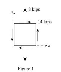
EBK MECHANICS OF MATERIALS, Chapter 11.3, Problem 39P , additional homework tip  1

Refer to Figure 1.

σx=8ksiσz=0τxz=14ksi

Apply the procedure to construct the Mohr’s circle as shown below.

  • Find the centre of the circle C located σavg=σx+σz2 from the origin.
  • Plot the reference points A having coordinates A(σx,τA).
  • Connect the point A with C and from the shaded triangle find the radius R of the circle.
  • Sketch the circle once R has been determined.

Construct the Mohr’s circle as shown below.

Calculate the centre of the circle (σavg) using average normal stress as shown below.

σavg=σx+σz2

Substitute 8ksi for σx and 0 for σz.

σavg=8+02=4ksi

The centre of the circle is C=4ksi.

Coordinates of the reference point z.

z=(σz,τxz)

Substitute 0 for σz and 14ksi for τxz.

z=(0, 14 ksi)

Coordinates of the reference point x.

x=(σx,τxz)

Substitute 8ksi for σx and 14ksi for τxz.

x=(8ksi,14ksi)

Calculate the radius (R) of the circle as shown below.

R=(σxσavg)2+(τxz)2

Substitute 8ksi for σx, 4ksi for σavg, and 14ksi for τxz.

R=(84)2+(14)2=212=14.56ksi

Sketch the Mohr’s circle as shown in Figure 2.
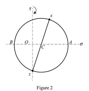
EBK MECHANICS OF MATERIALS, Chapter 11.3, Problem 39P , additional homework tip  2

Refer to Figure 2.

Calculate the principal stresses (σmaxand σmin) as shown below.

σmax,min=σavg±R

Substitute 4ksi for σavg and 14.56ksi for R.

σmax,min=4±14.56σa=18.56ksiσb=10.56ksi

Also the principal stress σc=σy.

Apply maximum distortion energy criterion as shown below.

(σaσb)2+(σbσc)2+(σcσa)2=2(σYF.S.)2 (1)

Substitute 18.56ksi for σa, 10.56ksi for σb, +16ksi for σc, 2.2 for F.S., and 65ksi for σY in Equation (1).

(18.56(10.56))2+((10.56)16)2+(1618.56)2=2×(65F.S.)2847.9744+705.4336+6.5536=8,450(F.S.)2(F.S.)2=5.4168F.S.=2.33

Hence, the factor of safety associated with the yield strength σz=+16ksi is F.S.=2.33_.

(b)

To determine

The factor of safety associated with the yield strength σz=16ksi.

(b)

Expert Solution
Check Mark

Answer to Problem 39P

The factor of safety associated with the yield strength σz=16ksi is F.S.=2.02_.

Explanation of Solution

Given information:

The stress component along x direction is σx=8ksi.

The stress component along z direction is σz=0.

The shear stress component is τxz=14ksi.

The yield stress is σY=65ksi.

The principal stress is σz=16ksi.

Calculation:

Refer to part (a).

The principal stresses σa=18.56ksi and σb=10.56MPa.

Apply maximum distortion energy criterion as shown below.

Substitute 18.56ksi for σa, 10.56ksi for σb, 16ksi for σc, 2.2 for F.S., and 65ksi for σY in Equation (1).

(18.56(10.56))2+((10.56)(16))2+((16)18.56)2=2×(65F.S.)2847.9744+29.5936+1,194.3936=8,450(F.S.)2(F.S.)2=4.0783F.S.=2.02

Therefore, the factor of safety associated with the yield strength σz=16ksi is F.S.=2.02_.

Want to see more full solutions like this?

Subscribe now to access step-by-step solutions to millions of textbook problems written by subject matter experts!
Students have asked these similar questions
need help?
A bent pipe is attached to a wall with brackets as shown. A force of F = 180 lb is applied to the end of the tube with direction indicated by the dimensions in the figure. Determine the support reactions at the brackets B, C, and D. Model these brackets as journal bearings (only force reactions perpendicular to the axis of the tube) and neglect couple moment reactions. Assume the distance between the supports at B and C and the tube bends nearby are negligible such that the support at C is directly above the support at D and the dimension g gives the distance between supports B and C. Enter your answers in Cartesian components. 2013 Michael Swanbom cc 10 BY NC SA g h א B 8° У A C x каж Values for dimensions on the figure are given in the table below. Note the figure may not be to scale. Variable Value a 6.72 in b 11.8 in с 14.8 in d 42.0 in h 26.6 in g 28.0 in → The reaction at B is B = lb. The reaction at C is C = lb. The reaction at D is D = lb. + << + + 2. + + 557 〈ん
The force F1 = 10 kN, F2 = 10 kN, F3 = 10 kN, F4 = 5 KN are acting on the sttructure shown. Determine the forces in the members specified below. Use positive values to indicate tension and negative values to indicate compression. F2 D b F1 F3 C E b F4 b B F a G Values for dimensions on the figure are given in the following table. Note the figure may not be to scale. Variable Value a 3 m b 4 m The force in member BC is KN. The force in member BE is KN. The force in member EF is KN.

Chapter 11 Solutions

EBK MECHANICS OF MATERIALS

Ch. 11.3 - A 30-in. length of aluminum pipe of...Ch. 11.3 - A single 6-mm-diameter steel pin B is used to...Ch. 11.3 - Prob. 13PCh. 11.3 - Prob. 14PCh. 11.3 - The assembly ABC is made of a steel for which E =...Ch. 11.3 - Show by integration that the strain energy of the...Ch. 11.3 - Prob. 17PCh. 11.3 - Prob. 18PCh. 11.3 - Prob. 19PCh. 11.3 - 11.18 through 11.21 In the truss shown, all...Ch. 11.3 - Prob. 21PCh. 11.3 - Each member of the truss shown is made of aluminum...Ch. 11.3 - Each member of the truss shown is made of aluminum...Ch. 11.3 - 11.24 through 11.27 Taking into account only the...Ch. 11.3 - Prob. 25PCh. 11.3 - 11.24 through 11.27 Taking into account only the...Ch. 11.3 - 11.24 through 11.27 Taking into account only the...Ch. 11.3 - Prob. 28PCh. 11.3 - Prob. 29PCh. 11.3 - Prob. 30PCh. 11.3 - 11.30 and 11.31 Using E = 200 GPa, determine the...Ch. 11.3 - Assuming that the prismatic beam AB has a...Ch. 11.3 - Prob. 33PCh. 11.3 - The design specifications for the steel shaft AB...Ch. 11.3 - Show by integration that the strain energy in the...Ch. 11.3 - The state of stress shown occurs in a machine...Ch. 11.3 - Prob. 37PCh. 11.3 - The state of stress shown occurs in a machine...Ch. 11.3 - Prob. 39PCh. 11.3 - Prob. 40PCh. 11.3 - Prob. 41PCh. 11.5 - A 5-kg collar D moves along the uniform rod AB and...Ch. 11.5 - The 18-lb cylindrical block E has a horizontal...Ch. 11.5 - The cylindrical block E has a speed v0 =16 ft/s...Ch. 11.5 - Prob. 45PCh. 11.5 - Prob. 46PCh. 11.5 - The 48-kg collar G is released from rest in the...Ch. 11.5 - Prob. 48PCh. 11.5 - Prob. 49PCh. 11.5 - Prob. 50PCh. 11.5 - Prob. 51PCh. 11.5 - The 2-kg block D is dropped from the position...Ch. 11.5 - The 10-kg block D is dropped from a height h = 450...Ch. 11.5 - Prob. 54PCh. 11.5 - A 160-lb diver jumps from a height of 20 in. onto...Ch. 11.5 - Prob. 56PCh. 11.5 - A block of weight W is dropped from a height h...Ch. 11.5 - 11.58 and 11.59 Using the method of work and...Ch. 11.5 - 11.58 and 11.59 Using the method of work and...Ch. 11.5 - 11.60 and 11.61 Using the method of work and...Ch. 11.5 - 11.60 and 11.61 Using the method of work and...Ch. 11.5 - 11.62 and 11.63 Using the method of work and...Ch. 11.5 - 11.62 and 11.63 Using the method of work and...Ch. 11.5 - Using the method of work and energy, determine the...Ch. 11.5 - Using the method of work and energy, determine the...Ch. 11.5 - The 20-mm diameter steel rod BC is attached to the...Ch. 11.5 - Torques of the same magnitude T are applied to the...Ch. 11.5 - Prob. 68PCh. 11.5 - The 20-mm-diameter steel rod CD is welded to the...Ch. 11.5 - The thin-walled hollow cylindrical member AB has a...Ch. 11.5 - 11.71 and 11.72 Each member of the truss shown has...Ch. 11.5 - 11.71 and 11.72 Each member of the truss shown has...Ch. 11.5 - Each member of the truss shown is made of steel...Ch. 11.5 - Each member of the truss shown is made of steel....Ch. 11.5 - Each member of the truss shown is made of steel...Ch. 11.5 - The steel rod BC has a 24-mm diameter and the...Ch. 11.9 - 11.77 and 11.78 Using the information in Appendix...Ch. 11.9 - 11.77 and 11.78 Using the information in Appendix...Ch. 11.9 - 11.79 through 11.82 For the beam and loading...Ch. 11.9 - 11.79 through 11.82 For the beam and loading...Ch. 11.9 - 11.79 through 11.82 For the beam and loading...Ch. 11.9 - 11.79 through 11.82 For the beam and loading...Ch. 11.9 - 11.83 through 11.85 For the prismatic beam shown,...Ch. 11.9 - 11.83 through 11.85 For the prismatic beam shown,...Ch. 11.9 - 11.83 through 11.85 For the prismatic beam shown,...Ch. 11.9 - 11.86 through 11.88 For the prismatic beam shown,...Ch. 11.9 - 11.86 through 11.88 For the prismatic beam shown,...Ch. 11.9 - 11.86 through 11.88 For the prismatic beam shown,...Ch. 11.9 - For the prismatic beam shown, determine the slope...Ch. 11.9 - For the prismatic beam shown, determine the slope...Ch. 11.9 - For the beam and loading shown, determine the...Ch. 11.9 - For the beam and loading shown, determine the...Ch. 11.9 - 11.93 and 11.94 For the beam and loading shown,...Ch. 11.9 - 11.93 and 11.94 For the beam and loading shown,...Ch. 11.9 - For the beam and loading shown, determine the...Ch. 11.9 - For the beam and loading shown, determine the...Ch. 11.9 - Prob. 97PCh. 11.9 - For the beam and loading shown, determine the...Ch. 11.9 - 11.99 and 11.100 For the truss and loading shown,...Ch. 11.9 - 11.99 and 11.100 For the truss and loading shown,...Ch. 11.9 - 11.101 and 11.102 Each member of the truss shown...Ch. 11.9 - 11.101 and 11.102 Each member of the truss shown...Ch. 11.9 - 11.103 and 11.104 Each member of the truss shown...Ch. 11.9 - 11.103 and 11 104 Each member of the truss shown...Ch. 11.9 - A uniform rod of flexural rigidity EI is bent and...Ch. 11.9 - For the uniform rod and loading shown and using...Ch. 11.9 - For the beam and loading shown and using...Ch. 11.9 - Two rods AB and BC of the same flexural rigidity...Ch. 11.9 - Three rods, each of the same flexural rigidity EI,...Ch. 11.9 - Three rods, each of the same flexural rigidity EI,...Ch. 11.9 - 11.111 through 11.115 Determine the reaction at...Ch. 11.9 - 11.111 through 11.115 Determine the reaction at...Ch. 11.9 - 11.111 through 11.115 Determine the reaction at...Ch. 11.9 - 11.111 through 11.115 Determine the reaction at...Ch. 11.9 - 11.111 through 11.115 Determine the reaction at...Ch. 11.9 - For the uniform beam and loading shown, determine...Ch. 11.9 - 11.117 through 11.120 Three members of the same...Ch. 11.9 - 11.117 through 11.120 Three members of the same...Ch. 11.9 - 11.117 through 11.120 Three members of the same...Ch. 11.9 - 11.117 through 11.120 Three members of the same...Ch. 11.9 - 11.121 and 11.122 Knowing that the eight members...Ch. 11.9 - 11.121 and 11.122 Knowing that the eight members...Ch. 11 - Rod AB is made of a steel for which the yield...Ch. 11 - Each member of the truss shown is made of steel...Ch. 11 - The ship at A has just started to drill for oil on...Ch. 11 - Collar D is released from rest in the position...Ch. 11 - Each member of the truss shown is made of steel...Ch. 11 - A block of weight W is placed in contact with a...Ch. 11 - Two solid steel shafts are connected by the gears...Ch. 11 - A 160-lb diver jumps from a height of 20 in. onto...Ch. 11 - For the prismatic beam shown, determine the slope...Ch. 11 - A disk of radius a has been welded to end B of the...Ch. 11 - A uniform rod of flexural rigidity EI is bent and...Ch. 11 - The steel bar ABC has a square cross section of...
Knowledge Booster
Background pattern image
Mechanical Engineering
Learn more about
Need a deep-dive on the concept behind this application? Look no further. Learn more about this topic, mechanical-engineering and related others by exploring similar questions and additional content below.
Similar questions
SEE MORE QUESTIONS
Recommended textbooks for you
Text book image
Elements Of Electromagnetics
Mechanical Engineering
ISBN:9780190698614
Author:Sadiku, Matthew N. O.
Publisher:Oxford University Press
Text book image
Mechanics of Materials (10th Edition)
Mechanical Engineering
ISBN:9780134319650
Author:Russell C. Hibbeler
Publisher:PEARSON
Text book image
Thermodynamics: An Engineering Approach
Mechanical Engineering
ISBN:9781259822674
Author:Yunus A. Cengel Dr., Michael A. Boles
Publisher:McGraw-Hill Education
Text book image
Control Systems Engineering
Mechanical Engineering
ISBN:9781118170519
Author:Norman S. Nise
Publisher:WILEY
Text book image
Mechanics of Materials (MindTap Course List)
Mechanical Engineering
ISBN:9781337093347
Author:Barry J. Goodno, James M. Gere
Publisher:Cengage Learning
Text book image
Engineering Mechanics: Statics
Mechanical Engineering
ISBN:9781118807330
Author:James L. Meriam, L. G. Kraige, J. N. Bolton
Publisher:WILEY
Understanding Failure Theories (Tresca, von Mises etc...); Author: The Efficient Engineer;https://www.youtube.com/watch?v=xkbQnBAOFEg;License: Standard youtube license