
Concept explainers
Videos
The 20-mm-diameter steel rod CD is welded to the 20-mm- diameter steel shaft AB as shown. End C of rod CD is touching the rigid surface shown when a couple TB is applied to a disk attached to shaft AB. Knowing that the bearings are self aligning and exert no couples on the shaft, determine the angle of rotation of the disk when TB = 400 N ∙ m. Use E = 200 GPa and G = 77.2 GPa. (Consider the strain energy due to both bending and twisting in shaft AB and to bending in arm CD.)
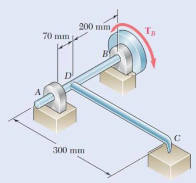
Fig. P11.69
The angle of rotation of the disk when
Answer to Problem 69P
The angle of rotation of the disk at B is
Explanation of Solution
Given information:
The diameter of the shaft AB and the steel rod CD is
The modulus of rigidity
The torque applied at B is
The modulus of elasticity
The length of steel rod CD is
The length of shaft AB is
Calculation:
Calculate the moment of inertia
Substitute
Consider the bending of rod CD.
Sketch the Free Body Diagram as shown in Figure 1.
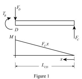
Refer to Figure 1.
Take moment about rod D is Equal to zero.
Substitute
Summation of forces along y direction is Equal to zero.
Calculate the bending moment at a distance x from C as shown below.
Calculate the strain energy as shown below.
For the steel rod CD.
Substitute
Consider the bending of shaft ADB.
Sketch the Free Body Diagram of the shaft as shown in Figure 2.
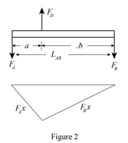
Refer to Figure 2.
Take moment about A is Equal to zero.
Take moment about B is Equal to zero.
Bending moment at a distance x from A
Bending moment at a distance x from B
Calculate the strain energy for shaft AB using Equation (1) as shown below.
Substitute
Substitute
Consider the portion DB of shaft ADB carries the torque.
Calculate the polar moment of inertia
Substitute
Calculate the strain energy
Substitute
Calculate the total strain energy
Substitute
Calculate the angle
Provide the work energy equation at disk B as shown below.
Substitute
Therefore, the angle of rotation of the disk at B is
Want to see more full solutions like this?
Chapter 11 Solutions
EBK MECHANICS OF MATERIALS


- 2. Figure below shows a U-tube manometer open at both ends and containing a column of liquid mercury of length l and specific weight y. Considering a small displacement x of the manometer meniscus from its equilibrium position (or datum), determine the equivalent spring constant associated with the restoring force. Datum Area, Aarrow_forward1. The consequences of a head-on collision of two automobiles can be studied by considering the impact of the automobile on a barrier, as shown in figure below. Construct a mathematical model (i.e., draw the diagram) by considering the masses of the automobile body, engine, transmission, and suspension and the elasticity of the bumpers, radiator, sheet metal body, driveline, and engine mounts.arrow_forward3.) 15.40 – Collar B moves up at constant velocity vB = 1.5 m/s. Rod AB has length = 1.2 m. The incline is at angle = 25°. Compute an expression for the angular velocity of rod AB, ė and the velocity of end A of the rod (✓✓) as a function of v₂,1,0,0. Then compute numerical answers for ȧ & y_ with 0 = 50°.arrow_forward
- 2.) 15.12 The assembly shown consists of the straight rod ABC which passes through and is welded to the grectangular plate DEFH. The assembly rotates about the axis AC with a constant angular velocity of 9 rad/s. Knowing that the motion when viewed from C is counterclockwise, determine the velocity and acceleration of corner F.arrow_forward500 Q3: The attachment shown in Fig.3 is made of 1040 HR. The static force is 30 kN. Specify the weldment (give the pattern, electrode number, type of weld, length of weld, and leg size). Fig. 3 All dimension in mm 30 kN 100 (10 Marks)arrow_forward(read image) (answer given)arrow_forward
- A cylinder and a disk are used as pulleys, as shown in the figure. Using the data given in the figure, if a body of mass m = 3 kg is released from rest after falling a height h 1.5 m, find: a) The velocity of the body. b) The angular velocity of the disk. c) The number of revolutions the cylinder has made. T₁ F Rd = 0.2 m md = 2 kg T T₂1 Rc = 0.4 m mc = 5 kg ☐ m = 3 kgarrow_forward(read image) (answer given)arrow_forward11-5. Compute all the dimensional changes for the steel bar when subjected to the loads shown. The proportional limit of the steel is 230 MPa. 265 kN 100 mm 600 kN 25 mm thickness X Z 600 kN 450 mm E=207×103 MPa; μ= 0.25 265 kNarrow_forward
- T₁ F Rd = 0.2 m md = 2 kg T₂ Tz1 Rc = 0.4 m mc = 5 kg m = 3 kgarrow_forward2. Find a basis of solutions by the Frobenius method. Try to identify the series as expansions of known functions. (x + 2)²y" + (x + 2)y' - y = 0 ; Hint: Let: z = x+2arrow_forward1. Find a power series solution in powers of x. y" - y' + x²y = 0arrow_forward
 Elements Of ElectromagneticsMechanical EngineeringISBN:9780190698614Author:Sadiku, Matthew N. O.Publisher:Oxford University Press
 Mechanics of Materials (10th Edition)Mechanical EngineeringISBN:9780134319650Author:Russell C. HibbelerPublisher:PEARSON
 Thermodynamics: An Engineering ApproachMechanical EngineeringISBN:9781259822674Author:Yunus A. Cengel Dr., Michael A. BolesPublisher:McGraw-Hill Education
 Control Systems EngineeringMechanical EngineeringISBN:9781118170519Author:Norman S. NisePublisher:WILEY
 Mechanics of Materials (MindTap Course List)Mechanical EngineeringISBN:9781337093347Author:Barry J. Goodno, James M. GerePublisher:Cengage Learning
 Engineering Mechanics: StaticsMechanical EngineeringISBN:9781118807330Author:James L. Meriam, L. G. Kraige, J. N. BoltonPublisher:WILEY