
Videos
Consider a two-stage cascade refrigeration cycle with a flash chamber as shown in the figure with refrigerant-134a as the working fluid. The evaporator temperature is −10°C and the condenser pressure is 1600 kPa. The refrigerant leaves the condenser as a saturated liquid and is throttled to a flash chamber operating at 0.45 MPa. Part of the refrigerant evaporates during this flashing process, and this vapor is mixed with the refrigerant leaving the low-pressure compressor. The mixture is then compressed to the condenser pressure by the high-pressure compressor. The liquid in the flash chamber is throttled to the evaporator pressure and cools the refrigerated space as it vaporizes in the evaporator. The mass flow rate of the refrigerant through the low-pressure compressor is 0.11 kg/s. Assuming the refrigerant leaves the evaporator as a saturated vapor and the isentropic efficiency is 86 percent for both compressors, determine (a) the mass flow rate of the refrigerant through the high-pressure compressor, (b) the rate of refrigeration supplied by the system, and (c) the COP of this refrigerator. Also, determine (d) the rate of refrigeration and the COP if this refrigerator operated on a single-stage vapor-compression cycle between the same evaporating temperature and condenser pressure with the same compressor efficiency and the same flow rate as calculated in part a.
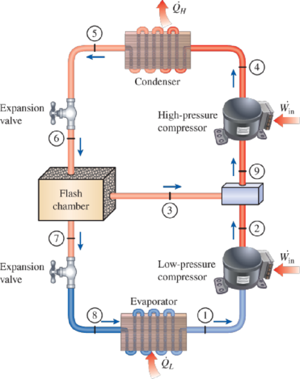
FIGURE P11–65
(a)
The mass flow rate of the refrigerant through the high-pressure compressor.
Answer to Problem 65P
The mass flow rate of the refrigerant through the high-pressure compressor is
Explanation of Solution
Show the T-s diagram as in Figure (1).
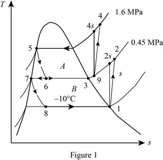
From Figure (1), write the specific enthalpy at state 6 is equal to state 5 due to throttling process.
Here, specific enthalpy at state 6 and 5 is
From Figure (1), write the specific enthalpy at state 8 is equal to state 7 due to throttling process.
Here, specific enthalpy at state 8 and 7 is
Express enthalpy at state 1.
Here, enthalpy saturation vapor at temperature of
Express entropy at state 1.
Here, entropy saturation vapor at temperature of
Express the specific enthalpy at state 2.
Here, specific enthalpy at state 2s is
Express enthalpy at state 3.
Here, enthalpy saturation vapor at pressure of
Express enthalpy at state 5.
Here, enthalpy saturation liquid at pressure of
Express enthalpy at state 7.
Here, enthalpy saturation liquid at pressure of
Express the quality at state 6.
Express the mass flow rate of the refrigerant.
Here, mass flow rate at state 7 is
Conclusion:
Refer Table A-11, “saturated refrigerant-134a-temperature table”, and write enthalpy saturation vapor at temperature of
Substitute
Refer Table A-11, “saturated refrigerant-134a-temperature table”, and write entropy saturation vapor at temperature of
Substitute
Perform the unit conversion of pressure at state 2 from
Refer Table A-13, “superheated refrigerant 134a”, and write the specific enthalpy at state 2s corresponding to pressure at state 2 of
Here, enthalpy at state 2s is
Substitute
Refer Table A-12, “saturated refrigerant-134a-pressure table”, and write the enthalpy saturation vapor at pressure of
Substitute
Refer Table A-12, “saturated refrigerant-134a-pressure table”, and write the enthalpy saturation liquid at pressure of
Substitute
Substitute
Refer Table A-12, “saturated refrigerant-134a-pressure table”, and write the enthalpy saturation liquid at pressure of
Substitute
Substitute
Substitute
Substitute
Hence, the mass flow rate of the refrigerant through the high-pressure compressor is
(b)
The rate of refrigeration supplied by the system.
Answer to Problem 65P
The rate of refrigeration supplied by the system is
Explanation of Solution
Express the mass flow rate at state 3.
Express the enthalpy at state 9.
Express the enthalpy at state 4.
Here, specific enthalpy at state 4s is
Express the rate of heat removal from the refrigerated space.
Conclusion:
Substitute
Substitute
Refer Table A-13, “superheated refrigerant 134a”, and write the specific enthalpy at state 9 corresponding to pressure at state 9 of
Here, entropy at state 9 is
Refer Table A-13, “superheated refrigerant 134a”, and write the specific enthalpy at state 4s corresponding to pressure at state 4 of
Write the formula of interpolation method of two variables.
Here, the variables denote by x and y is specific entropy at state 9 and specific enthalpy at state 4s respectively.
Show the specific enthalpy at state 4s corresponding to specific entropy as in Table (1).
|
Specific entropy at state 9 |
Specific enthalpy at state 4s |
| 0.9164 | 280.71 |
| 0.9399 | |
| 0.9536 | 293.27 |
Substitute
Thus, the specific enthalpy at state 4s is,
Substitute
Substitute
Hence, the rate of refrigeration supplied by the system is
(c)
The COP of the refrigerator.
Answer to Problem 65P
The COP of the refrigerator is
Explanation of Solution
Express the power input.
Express the coefficient of performance.
Conclusion:
Substitute
Substitute
Hence, the coefficient of performance of the refrigerator is
(d)
The rate of refrigeration and the COP of the refrigerator.
Answer to Problem 65P
The rate of refrigeration is
Explanation of Solution
Show the T-s diagram as in Figure (1).
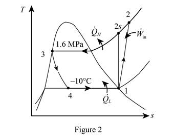
From Figure (1), write the specific enthalpy at state 4 is equal to state 3 due to throttling process.
Here, specific enthalpy at state 4 and 3 is
Express the enthalpy at state 2.
Here, specific enthalpy at state 2s is
Express enthalpy at state 3.
Here, enthalpy saturation vapor at pressure of
Express the rate of refrigeration.
Express the rate of work input.
Express the coefficient of performance.
Conclusion:
Refer Table A-13, “superheated refrigerant 134a”, and write the specific enthalpy at state 2s corresponding to pressure at state 2 of
Show the specific enthalpy at state 2s corresponding to specific entropy as in Table (2).
|
Specific entropy at state 2 |
Specific enthalpy at state 2s |
| 0.9164 | 280.71 |
| 0.9378 | |
| 0.9536 | 293.27 |
Use excels and tabulates the values from Table (2) in Equation (XV) to get,
Thus, the specific enthalpy at state 2s is,
Substitute
Refer Table A-12, “saturated refrigerant-134a-pressure table”, and write the enthalpy saturation liquid at pressure of
Substitute
Substitute
Substitute
Hence, the rate of refrigeration is
Substitute
Substitute
Hence, the coefficient of performance of the refrigerator is
Want to see more full solutions like this?
Chapter 11 Solutions
CONNECT FOR THERMODYNAMICS: AN ENGINEERI


- AAA Show laplace transform on 1; (+) to L (y(+)) : SY(s) = x (0) Y(s) = £ [lx (+)] = 5 x(+) · est de 2 -St L [ y (^) ] = So KG) et de D 2 D D AA Y(A) → Y(s) Ŷ (+) → s Y(s) -yarrow_forward1) In each of the following scenarios, based on the plane of impact (shown with an (n, t)) and the motion of mass 1, draw the direction of motion of mass 2 after the impact. Note that in all scenarios, mass 2 is initially at rest. What can you say about the nature of the motion of mass 2 regardless of the scenario? m1 15 <+ m2 2) y "L χ m1 m2 m1 בז m2 Farrow_forward8. In the following check to see if the set S is a vector subspace of the corresponding Rn. If it is not, explain why not. If it is, then find a basis and the dimension. X1 (a) S = X2 {[2], n ≤ n } c X1 X2 CR² X1 (b) S X2 = X3 X4 x1 + x2 x3 = 0arrow_forward
- 2) Suppose that two unequal masses m₁ and m₂ are moving with initial velocities V₁ and V₂, respectively. The masses hit each other and have a coefficient of restitution e. After the impact, mass 1 and 2 head to their respective gaps at angles a and ẞ, respectively. Derive expressions for each of the angles in terms of the initial velocities and the coefficient of restitution. m1 m2 8 m1 ↑ บา m2 ñ Вarrow_forwardThe fallowing question is from a reeds book on applied heat i am studying. Although the answer is provided, im struggling to understand the whole answer and the formulas and the steps theyre using. Also where some ov the values such as Hg and Hf come from in part i for example. Please explain step per step in detail thanks In an NH, refrigerator, the ammonia leaves the evaporatorand enters the cornpressor as dry saturated vapour at 2.68 bar,it leaves the compressor and enters the condenser at 8.57 bar with50" of superheat. it is condensed at constant pressure and leavesthe condenser as saturated liquid. If the rate of flow of the refrigerantthrough the circuit is 0.45 kglmin calculate (i) the compressorpower, (ii) the heat rejected to the condenser cooling water in kJ/s,an (iii) the refrigerating effect in kJ/s. From tables page 12, NH,:2.68 bar, hg= 1430.58.57 bar, hf = 275.1 h supht 50" = 1597.2Mass flow of refrigerant--- - - 0.0075 kgls 60Enthalpy gain per kg of refrigerant in…arrow_forwardstate the formulas for calculating work done by gasarrow_forward
- Exercises Find the solution of the following Differential Equations 1) y" + y = 3x² 3) "+2y+3y=27x 5) y"+y=6sin(x) 7) y"+4y+4y = 18 cosh(x) 9) (4)-5y"+4y = 10 cos(x) 11) y"+y=x²+x 13) y"-2y+y=e* 15) y+2y"-y'-2y=1-4x³ 2) y"+2y' + y = x² 4) "+y=-30 sin(4x) 6) y"+4y+3y=sin(x)+2 cos(x) 8) y"-2y+2y= 2e* cos(x) 10) y+y-2y=3e* 12) y"-y=e* 14) y"+y+y=x+4x³ +12x² 16) y"-2y+2y=2e* cos(x)arrow_forwardThe state of stress at a point is σ = -4.00 kpsi, σy = 16.00 kpsi, σ = -14.00 kpsi, Try = 11.00 kpsi, Tyz = 8.000 kpsi, and T = -14.00 kpsi. Determine the principal stresses. The principal normal stress σ₁ is determined to be [ The principal normal stress σ2 is determined to be [ The principal normal stress σ3 is determined to be kpsi. kpsi. The principal shear stress 71/2 is determined to be [ The principal shear stress 7½ is determined to be [ The principal shear stress T₁/, is determined to be [ kpsi. kpsi. kpsi. kpsi.arrow_forwardRepeat Problem 28, except using a shaft that is rotatingand transmitting a torque of 150 N * m from the left bearing to the middle of the shaft. Also, there is a profile keyseat at the middle under the load. (I want to understand this problem)arrow_forward
- Prob 2. The material distorts into the dashed position shown. Determine the average normal strains &x, Ey and the shear strain Yxy at A, and the average normal strain along line BE. 50 mm B 200 mm 15 mm 30 mm D ΕΙ 50 mm x A 150 mm Farrow_forwardProb 3. The triangular plate is fixed at its base, and its apex A is given a horizontal displacement of 5 mm. Determine the shear strain, Yxy, at A. Prob 4. The triangular plate is fixed at its base, and its apex A is given a horizontal displacement of 5 mm. Determine the average normal strain & along the x axis. Prob 5. The triangular plate is fixed at its base, and its apex A is given a horizontal displacement of 5 mm. Determine the average normal strain &x along the x' axis. x' 45° 800 mm 45° 45% 800 mm 5 mmarrow_forwardAn airplane lands on the straight runaway, originally travelling at 110 ft/s when s = 0. If it is subjected to the decelerations shown, determine the time t' needed to stop the plane and construct the s -t graph for the motion. draw a graph and show all work step by steparrow_forward
 Refrigeration and Air Conditioning Technology (Mi...Mechanical EngineeringISBN:9781305578296Author:John Tomczyk, Eugene Silberstein, Bill Whitman, Bill JohnsonPublisher:Cengage Learning