Mechanics of Materials
9th Edition
ISBN: 9780133254426
Author: Russell C. Hibbeler
Publisher: Prentice Hall
expand_more
expand_more
format_list_bulleted
Textbook Question
Chapter 11, Problem 11.54RP
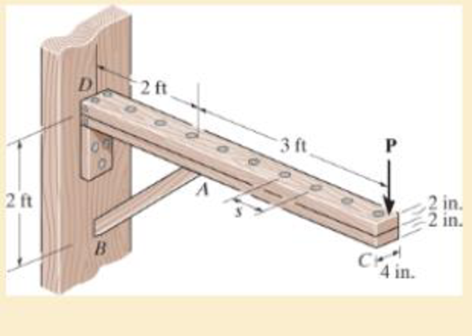
by 4-in. pieces of wood braced as shown. If the allowable bending stress is σallow = 600 psi, determine the largest load P that can be applied. Also, determine the maximum spacing of nails, s, along the beam section AC if each nail can resist a shear force of 800 lb. Assume the beam is pin connected at A, B, and D. Neglect the axial force developed in the beam along DA.

Expert Solution & Answer
Want to see the full answer?
Check out a sample textbook solution
Students have asked these similar questions
Q4/ A compressor is driven motor by mean of a flat belt of thickness 10 mm and a width of
250 mm. The motor pulley is 300 mm diameter and run at 900 rpm and the compressor
pulley is 1500 mm diameter. The shaft center distance is 1.5 m. The angle of contact of
the smaller pulley is 220° and on the larger pulley is 270°. The coefficient of friction
between the belt and the small pulley is 0.3, and between the belt and the large pulley is
0.25. The maximum allowable belt stress is 2 MPa and the belt density is 970 kg/m³.
(a) What is the power capacity of the drive and (b) If the small pulley replaced by
V-grooved pulley of diameter 300 mm, grooved angle of 34° and the coefficient of
friction between belt and grooved pulley is 0.35. What will be the power capacity in this
case, assuming that the diameter of the large pulley remain the same of 1500 mm.
You are tasked with designing a power drive system to transmit power between a motor and a conveyor belt in a manufacturing facility as illustrated in figure.
The design must ensure efficient power transmission, reliability, and safety. Given the following specifications and constraints, design drive system for this application:
Specifications:
Motor Power: The electric motor provides 10 kW of power at 1,500 RPM.
Output Speed: The output shaft should rotate at 150 rpm.
Design Decisions:
Transmission ratio: Determine the necessary drive ratio for the system.
Shaft Diameter: Design the shafts for both the motor and the conveyor end.
Material Selection: Choose appropriate materials for the gears, shafts.
Bearings: Select suitable rolling element bearings.
Constraints:
Space Limitation:
The available space for the gear drive system is limited to a 1-meter-long section.
Attribute 4 of CEP
Depth of knowledge required
Fundamentals-based, first principles analytical approach…
- |
العنوان
In non-continuous dieless drawing process for copper tube as shown in Fig. (1), take the
following data: Do-20mm, to=3mm, D=12mm, ti/to=0.6 and v.-15mm/s. Calculate: (1)
area reduction RA, (2) drawing velocity v. Knowing that: ti: final thickness
V.
Fig. (1)
ofthre
Chapter 11 Solutions
Mechanics of Materials
Ch. 11.2 - Determine the minimum dimension a to the nearest...Ch. 11.2 - of the rod to safely support the load. The rod is...Ch. 11.2 - The wood has an allowable normal stress of allow =...Ch. 11.2 - of the beam's cross section to safely support the...Ch. 11.2 - Determine the minimum dimension b to the nearest...Ch. 11.2 - The beam is made of steel having an allowable...Ch. 11.2 - Determine its dimensions if it is to be...Ch. 11.2 - Determine the minimum width of the beam to the...Ch. 11.2 - if P=10 kip.Ch. 11.2 - If the allowable bending stress is allow = 22 ksi...
Ch. 11.2 - The allowable bending stress is allow = 24 ksi and...Ch. 11.2 - The allowable bending stress is allow = 22 ksi and...Ch. 11.2 - 11–7. Draw the shear and moment diagrams for the...Ch. 11.2 - *11–8. The simply supported beam is made of timber...Ch. 11.2 - The beam has an allowable normal stress of allow =...Ch. 11.2 - The beam has an allowable normal stress of allow...Ch. 11.2 - 11–11. The timber beam is to be loaded as shown....Ch. 11.2 - If each beam is to be designed to carry 90 lb/ft...Ch. 11.2 - 11–13. Select the lightest steel wide-flange beam...Ch. 11.2 - 11–14. Select the lightest-weight steel...Ch. 11.2 - Prob. 11.15PCh. 11.2 - The beam has an allowable normal stress of allow....Ch. 11.2 - Determine the maximum cable force P that can...Ch. 11.2 - to safely support the load. The wood has an...Ch. 11.2 - and the wood has an allowable normal stress of...Ch. 11.2 - Prob. 11.20PCh. 11.2 - Prob. 11.21PCh. 11.2 - Prob. 11.22PCh. 11.2 - 11–23. The beam is constructed from three boards...Ch. 11.2 - Prob. 11.24PCh. 11.2 - Prob. 11.25PCh. 11.2 - Select the lightest-weight wide-flange beam from...Ch. 11.2 - Prob. 11.27PCh. 11.2 - * 11–28. The joist AB used in housing construction...Ch. 11.2 - If the maximum bending stress is not to exceed...Ch. 11.2 - 11–30. The simply supported beam supports a load...Ch. 11.4 - Determine the variation in the width was a...Ch. 11.4 - Prob. 11.32PCh. 11.4 - Prob. 11.33PCh. 11.4 - The beam is made from a plate that has a constant...Ch. 11.4 - Determine the variation in the depth d of a...Ch. 11.4 - Determine the variation of the radius r of the...Ch. 11.4 - Prob. 11.37PCh. 11.4 - Determine the variation in the width b as a...Ch. 11.4 - The tubular shaft has an inner diameter of 15 mm....Ch. 11.4 - Prob. 11.40PCh. 11.4 - Prob. 11.41PCh. 11.4 - Prob. 11.42PCh. 11.4 - Prob. 11.43PCh. 11.4 - Prob. 11.44PCh. 11.4 - Prob. 11.45PCh. 11.4 - Prob. 11.46PCh. 11 - The cantilevered beam has a circular cross...Ch. 11 - Select the lightest-weight wide-flange overhanging...Ch. 11 - Prob. 11.49RPCh. 11 - Determine the shaft's diameter to the nearest...Ch. 11 - Select the lightest-weight wide-flange beam from...Ch. 11 - The simply supported joist is used in the...Ch. 11 - The simply supported joist is used in the...Ch. 11 - by 4-in. pieces of wood braced as shown. If the...
Additional Engineering Textbook Solutions
Find more solutions based on key concepts
CONCEPT QUESTIONS
15.CQ3 The ball rolls without slipping on the fixed surface as shown. What is the direction ...
Vector Mechanics for Engineers: Statics and Dynamics
17–1C A high-speed aircraft is cruising in still air. How does the temperature of air at the nose of the aircra...
Thermodynamics: An Engineering Approach
Assume a telephone signal travels through a cable at two-thirds the speed of light. How long does it take the s...
Electric Circuits. (11th Edition)
How is the hydrodynamic entry length defined for flow in a pipe? Is the entry length longer in laminar or turbu...
Fluid Mechanics: Fundamentals and Applications
1.2 Explain the difference between geodetic and plane
surveys,
Elementary Surveying: An Introduction To Geomatics (15th Edition)
How are relationships between tables expressed in a relational database?
Modern Database Management
Knowledge Booster
Learn more about
Need a deep-dive on the concept behind this application? Look no further. Learn more about this topic, mechanical-engineering and related others by exploring similar questions and additional content below.Similar questions
- A direct extrusion operation produces the cross section shown in Fig. (2) from an aluminum billet whose diameter 160 mm and length - 700 mm. Determine the length of the extruded section at the end of the operation if the die angle -14° 60 X Fig. (2) Note: all dimensions in mm.arrow_forwardFor hot rolling processes, show that the average strain rate can be given as: = (1+5)√RdIn(+1)arrow_forward: +0 usão العنوان on to A vertical true centrifugal casting process is used to produce bushings that are 250 mm long and 200 mm in outside diameter. If the rotational speed during solidification is 500 rev/min, determine the inside radii at the top and bottom of the bushing if R-2R. Take: -9.81 mis ۲/۱ ostrararrow_forward
- : +0 العنوان use only In conventional drawing of a stainless steel wire, the original diameter D.-3mm, the area reduction at each die stand r-40%, and the proposed final diameter D.-0.5mm, how many die stands are required to complete this process. онarrow_forwardIn non-continuous dieless drawing process for copper tube as shown in Fig. (1), take the following data: Do-20mm, to=3mm, D=12mm, ti/to=0.6 and vo-15mm/s. Calculate: (1) area reduction RA, (2) drawing velocity v. Knowing that: t₁: final thickness D₁ V. Fig. (1) Darrow_forwardA vertical true centrifugal casting process is used to produce bushings that are 250 mm long and 200 mm in outside diameter. If the rotational speed during solidification is 500 rev/min, determine the inside radii at the top and bottom of the bushing if R-2Rb. Take: 8-9.81 m/sarrow_forward
- In conventional drawing of a stainless steel wire, the original diameter D.-3mm, the area reduction at each die stand r-40%, and the proposed final diameter D₁-0.5mm, how many die stands are required to complete this process.arrow_forwardA vertical true centrifugal casting process is used to produce bushings that are 250 mm long and 200 mm in outside diameter. If the rotational speed during solidification is 500 rev/min, determine the inside radii at the top and bottom of the bushing if R-2Rb. Take: 8-9.81 m/sarrow_forwardIn non-continuous dieless drawing process for copper tube as shown in Fig. (1), take the following data: Do-20mm, to=3mm, D=12mm, ti/to=0.6 and vo-15mm/s. Calculate: (1) area reduction RA, (2) drawing velocity v. Knowing that: t₁: final thickness D₁ V. Fig. (1) Darrow_forward
- -6- 8 من 8 Mechanical vibration HW-prob-1 lecture 8 By: Lecturer Mohammed O. attea The 8-lb body is released from rest a distance xo to the right of the equilibrium position. Determine the displacement x as a function of time t, where t = 0 is the time of release. c=2.5 lb-sec/ft wwwww k-3 lb/in. 8 lb Prob. -2 Find the value of (c) if the system is critically damping. Prob-3 Find Meq and Ceq at point B, Drive eq. of motion for the system below. Ш H -7~ + 目 T T & T тт +arrow_forwardQ For the following plan of building foundation, Determine immediate settlement at points (A) and (B) knowing that: E,-25MPa, u=0.3, Depth of foundation (D) =1m, Depth of layer below base level of foundation (H)=10m. 3m 2m 100kPa A 2m 150kPa 5m 200kPa Barrow_forwardW PE 2 43 R² 80 + 10 + kr³ Ø8=0 +0 R²+J+ kr200 R² + J-) + k r² = 0 kr20 kr20 8+ W₁ = = 0 R²+1) R²+J+) 4 lec 8.pdf Mechanical vibration lecture 6 By: Lecturer Mohammed C. Attea HW1 (Energy method) Find equation of motion and natural frequency for the system shown in fig. by energy method. m. Jo 000 HW2// For the system Fig below find 1-F.B.D 2Eq.of motion 8 wn 4-0 (1) -5- marrow_forward
arrow_back_ios
SEE MORE QUESTIONS
arrow_forward_ios
Recommended textbooks for you
 Elements Of ElectromagneticsMechanical EngineeringISBN:9780190698614Author:Sadiku, Matthew N. O.Publisher:Oxford University Press
 Mechanics of Materials (10th Edition)Mechanical EngineeringISBN:9780134319650Author:Russell C. HibbelerPublisher:PEARSON
 Thermodynamics: An Engineering ApproachMechanical EngineeringISBN:9781259822674Author:Yunus A. Cengel Dr., Michael A. BolesPublisher:McGraw-Hill Education
 Control Systems EngineeringMechanical EngineeringISBN:9781118170519Author:Norman S. NisePublisher:WILEY
 Mechanics of Materials (MindTap Course List)Mechanical EngineeringISBN:9781337093347Author:Barry J. Goodno, James M. GerePublisher:Cengage Learning
 Engineering Mechanics: StaticsMechanical EngineeringISBN:9781118807330Author:James L. Meriam, L. G. Kraige, J. N. BoltonPublisher:WILEY

Elements Of Electromagnetics
Mechanical Engineering
ISBN:9780190698614
Author:Sadiku, Matthew N. O.
Publisher:Oxford University Press

Mechanics of Materials (10th Edition)
Mechanical Engineering
ISBN:9780134319650
Author:Russell C. Hibbeler
Publisher:PEARSON

Thermodynamics: An Engineering Approach
Mechanical Engineering
ISBN:9781259822674
Author:Yunus A. Cengel Dr., Michael A. Boles
Publisher:McGraw-Hill Education

Control Systems Engineering
Mechanical Engineering
ISBN:9781118170519
Author:Norman S. Nise
Publisher:WILEY

Mechanics of Materials (MindTap Course List)
Mechanical Engineering
ISBN:9781337093347
Author:Barry J. Goodno, James M. Gere
Publisher:Cengage Learning

Engineering Mechanics: Statics
Mechanical Engineering
ISBN:9781118807330
Author:James L. Meriam, L. G. Kraige, J. N. Bolton
Publisher:WILEY
Mechanics of Materials Lecture: Beam Design; Author: UWMC Engineering;https://www.youtube.com/watch?v=-wVs5pvQPm4;License: Standard Youtube License