
Concept explainers
Videos
(a)
To select:
The pump that runs at the given speed performing the task with efficiency being maximum.
Answer to Problem 11.4CP
The pump that runs at the given speed performing the task with efficiency being maximum is determined below.
Explanation of Solution
Given Information:
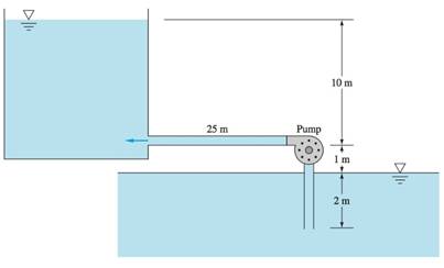
The given figure,

The system delivers 20-degree Celsius water from the sea level reservoir to another iron pipe with diameter 38 cm.
Minor loss before pump entrance
Minor loss after pump entrance
Concept Used:
Velocity of the flow:
Calculation:
According to the figure:
Reynold’s number:
Density
Dynamic Viscosity
Diameter=380mm
Volume=12.24m/s
Substituting the values:
The flow is turbulent.
Friction factor is given as:
Head loss using the friction factor is calculated.
Using equation (1)
Frictional heal loss is calculated using flow rates having different values:
| Q(gal/min) | 4000 | 8000 | 12000 | 16000 | 20000 | 22000 | 24000 |
| |
44 | 66 | 103 | 156 | 223 | 262 | 305 |
From the table and the reference figure at the flow rate of 20,000 gal/min, 88% efficiency. Hence the pump is given as 38 in.
Conclusion:
Thus, the pump that runs at the given speed performing the task with efficiency being maximum is determined.
(b)
To calculate:
The flow rate.
Answer to Problem 11.4CP
The flow rate is given as 20,000 gal/min
Explanation of Solution
Given Information:
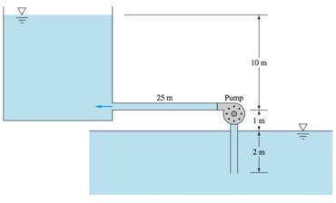
The given figure:
The system delivers 20-degree Celsius water from the sea level reservoir to another iron pipe with diameter 38 cm.
Minor loss before pump entrance
Minor loss after pump entrance
Concept Used:
Velocity of the flow:
Calculation:
Reynold’s number
Density
Dynamic Viscosity
Diameter=380mm
Volume=12.24m/s
Substituting the values:
The flow is turbulent.
Friction factor is given as:
Head loss using the friction factor is calculated:
Using equation (1)
Frictional heal loss is calculated using flow rates having different values:
| Q(gal/min) | 4000 | 8000 | 12000 | 16000 | 20000 | 22000 | 24000 |
| |
44 | 66 | 103 | 156 | 223 | 262 | 305 |
Conclusion:
Thus, the flow rate is determined.
(c)
Brake horse power.
Answer to Problem 11.4CP
Brake horse power=1250hp
Explanation of Solution
Given Information:
The given figure,

The system delivers 20-degree Celsius water from the sea level reservoir to another iron pipe with diameter 38 cm.
Minor loss before pump entrance
Minor loss after pump entrance
Concept Used:
Calculation:
Substituting we have:
Conclusion:
Thus, the brake horse power is calculated.
(d)
The given pump is safe from cavitation.
Answer to Problem 11.4CP
The pump replacement is needed as the pump will cavitate.
Explanation of Solution
Given Information:
The given figure:
The system delivers 20-degree Celsius water from the sea level reservoir to another iron pipe with diameter 38 cm.
Minor loss before pump entrance
Minor loss after pump entrance
Concept Used:
Calculation:
Substituting we have:
For the flow rate Q=20000gal/min, the NPSH=16m(-0.36m).
So, the pump cavitates.
Conclusion:
Thus, the given pump is safe from cavitation is determined.
Want to see more full solutions like this?
Chapter 11 Solutions
Fluid Mechanics, 8 Ed


- 2nd Law of Thermodynamics A 1.5-ft3 rigid tank contains saturated refrigerant-134 at 170 psia. Initially, 20 percent of the volume isoccupied by liquid and the rest by vapor. A valve at the top of the tank is now opened, and vapor is allowedto escape slowly from the tank. Heat is transferred to the refrigerant such that the pressure inside the tankremains constant. The valve is closed when the last drop of liquid in the tank is vaporized. Determine thetotal heat transfer for this process.arrow_forwardDraw the shear and bending-moment diagrams for the beam and loading shown, and determine the maximum normal stress due to bending. 4.8 kips/ft 32 kips B C D E I Hinge 8 ft. 2 ft 5 ft 5 ft W12 x 40arrow_forward2nd Law of Thermodynamics A rigid, insulated tank that is initially evacuated is connected through a valve to the supply line that carrieshelium at 300 kPa and 140◦C. Now the valve is opened, and helium is allowed to flow into the tank until thepressure reaches 300 kPa, at which point the valve is closed. Determine the flow work of the helium in thesupply line and the final temperature of the helium in the tank.arrow_forward
- Draw the shear and bending-moment diagrams for the beam and loading shown, and determine the maximum normal stress due to bending. 5 kips 10 kips B I W14 x 22 -5 ft -8 ft 5 ft-arrow_forward2nd Law of Thermodynamics Liquid water at 200 kPa and 25◦C is heated in a chamber by mixing it with superheated steam at 200 kPaand 250◦C. cold water enters the chamber at a rate of 2 kg/s. If the mixture leaves the mixing chamber at50◦C, determine the mass flow rate of the superheated steam required.arrow_forwardThe 2nd Law of Thermodynamics Refrigerant-134a enters the compressor of a refrigeration system as saturated vapor at 0.16 MPa, and leavesas superheated vapor at 0.9 MPa and 70◦C at a rate of 0.08 kg/s. Determine the rates of energy transfers bymass into and out of the compressor. Assume the kinetic and potential energies are negligible.arrow_forward
- 2nd Law of Thermodynamics Water enters the tubes of a cold plate at 65◦C with an average velocity of 50 ft/min and leaves at 110◦F. Thediameter of the tubes is 0.2 in. Assuming 20 percent of the heat generated is dissipated from the componentsto the surroundings by convection and radiation, and the remaining 80 percent is removed by the coolingwater, determine the amount of heat generated by the electronic devices mounted on the cold plate.arrow_forwardThe 2nd Law of Thermodynamics Refrigerant-134a enters a diffuser steadily as saturated vapor 500 kPa with a velocity of 170 m/s, and it leavesat 600 kPa and 50◦C. the refrigerant is gaining heat at a rate of 2.5 kJ/s as it passes through the diffuser. Ifthe exit area is 75 percent greater than the inlet area, determine (a) the exit velocity (b) the mass flow rate of the refrigerant.arrow_forward2nd Law of Thermodynamics Refrigerant-134a is throttled from the saturated liquid state at 850 kPa to a pressure of 200 kPa. Determinethe temperature drop during this process and the final specific volume of the refrigerant.arrow_forward
- 2nd Law of Thermodynamics An adiabatic gas turbine expands air at 1350 kPa and 525◦C to 125 kPa and 130◦C. Air enters the tur-bine through a 0.15-m2 opening with an average velocity of 50 m/s, and exhausts through a 1-m2 opening.Determine (a) the mass flow rate of air through the turbine (b) the power produced by the turbine.arrow_forwardThe 2nd Law of Thermodynamics Air is compressed from 12 psia and 77.3◦F to a pressure of 145 psia while being cooled at a rate of 15Btu/lbm by circulating water through the compressor casing. The volume flow rate of the air at the inletconditions is 6000 ft3/min, and the power input to the compressor is 800 hp. Determine (a) the mass flow rate of the air (b) the temperature at the compressor exitarrow_forwardI need solution by handarrow_forward
 Elements Of ElectromagneticsMechanical EngineeringISBN:9780190698614Author:Sadiku, Matthew N. O.Publisher:Oxford University Press
 Mechanics of Materials (10th Edition)Mechanical EngineeringISBN:9780134319650Author:Russell C. HibbelerPublisher:PEARSON
 Thermodynamics: An Engineering ApproachMechanical EngineeringISBN:9781259822674Author:Yunus A. Cengel Dr., Michael A. BolesPublisher:McGraw-Hill Education
 Control Systems EngineeringMechanical EngineeringISBN:9781118170519Author:Norman S. NisePublisher:WILEY
 Mechanics of Materials (MindTap Course List)Mechanical EngineeringISBN:9781337093347Author:Barry J. Goodno, James M. GerePublisher:Cengage Learning
 Engineering Mechanics: StaticsMechanical EngineeringISBN:9781118807330Author:James L. Meriam, L. G. Kraige, J. N. BoltonPublisher:WILEY