
Vector Mechanics for Engineers: Statics
12th Edition
ISBN: 9781259977244
Author: BEER
Publisher: MCG
expand_more
expand_more
format_list_bulleted
Concept explainers
Videos
Textbook Question
Chapter 10.2, Problem 10.86P
10.85 and 10.86 Cart B, which weighs 75 kN, rolls along a sloping and track that forms an angle β with the horizontal. The spring constant is 5 kN/m, and the spring is unstretched when x = 0. Determine the distance x corresponding to equilibrium for the angle β indicated.
10.85 Angle β = 30°
10.86 Angle β = 60°
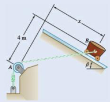
Fig. P10.85 and P10.86
Expert Solution & Answer
Want to see the full answer?
Check out a sample textbook solution
Students have asked these similar questions
Determine the distance h that the column of mercury in the tube will be depressed when the tube is inserted into the mercury at a room temperature of 68 F. Plot this relationship of h (vertical axis) versus D for 0.5 in≤D≤0.150in. Give values for increments of ΔD=0.025in. Discuss this result
Water is at a temperature of 30 C. Plot the height h of the water as a function of the gap w between the two glass plates for 0.4 mm ≤ w ≤ 2.4 mm. Use increments of 0.4mm. Take sigma=0.0718 N/m.
What is the reading on the vernier calipers?
7
6
0 5
10
8
Chapter 10 Solutions
Vector Mechanics for Engineers: Statics
Ch. 10.1 - Determine the vertical force P that must be...Ch. 10.1 - Determine the horizontal force P that must be...Ch. 10.1 - Prob. 10.3PCh. 10.1 - 10.3 and 10.4 Determine the couple M that must be...Ch. 10.1 - A spring of constant 15 kN/m connects points C and...Ch. 10.1 - A spring of constant 15 kN/m connects points C and...Ch. 10.1 - The two-bar linkage shown is supported by a pin...Ch. 10.1 - Determine the weight W that balances the 10-lb...Ch. 10.1 - Prob. 10.9PCh. 10.1 - Prob. 10.10P
Ch. 10.1 - Prob. 10.11PCh. 10.1 - Knowing that the line of action of the force Q...Ch. 10.1 - Solve Prob. 10.12 assuming that the force P...Ch. 10.1 - The mechanism shown is acted upon by the force P....Ch. 10.1 - Prob. 10.15PCh. 10.1 - 10.15 and 10.16 Derive an expression for the...Ch. 10.1 - A uniform rod AB with length l and weight W is...Ch. 10.1 - The pin at C is attached to member BCD and can...Ch. 10.1 - For the linkage shown, determine the couple M...Ch. 10.1 - For the linkage shown, determine the force...Ch. 10.1 - A 4-kN force P is applied as shown to the piston...Ch. 10.1 - A couple M with a magnitude of 100 Nm isapplied as...Ch. 10.1 - Rod AB is attached to a block at A that can...Ch. 10.1 - Solve Prob. 10.23, assuming that the 800-N force...Ch. 10.1 - Prob. 10.25PCh. 10.1 - Determine the value of corresponding to...Ch. 10.1 - Prob. 10.27PCh. 10.1 - Determine the value of corresponding to...Ch. 10.1 - Prob. 10.29PCh. 10.1 - Two rods AC and CE are connected by a pin at Cand...Ch. 10.1 - Solve Prob. 10.30 assuming that force P is movedto...Ch. 10.1 - Two bars AD and DG are connected by a pin at Dand...Ch. 10.1 - Solve Prob. 10.32 assuming that the 900-N...Ch. 10.1 - Two 5-kg bars AB and BC are connected by a pin atB...Ch. 10.1 - A vertical force P with a magnitude of 150 N...Ch. 10.1 - Prob. 10.36PCh. 10.1 - 10.37 and 10.38 Knowing that the constant of...Ch. 10.1 - Prob. 10.38PCh. 10.1 - The lever AB is attached to the horizontal shaft...Ch. 10.1 - Solve Prob. 10.39, assuming that P = 350 N, l =250...Ch. 10.1 - Prob. 10.41PCh. 10.1 - The position of boom ABC is controlled by...Ch. 10.1 - The position of member ABC is controlled by the...Ch. 10.1 - The position of member ABC is controlled by...Ch. 10.1 - The telescoping arm ABC is used to provide...Ch. 10.1 - Solve Prob. 10.45, assuming that the workers...Ch. 10.1 - Denoting the coefficient of static friction...Ch. 10.1 - Knowing that the coefficient of static...Ch. 10.1 - A block with weight W is pulled up a plane forming...Ch. 10.1 - Derive an expression for the mechanical...Ch. 10.1 - Denoting the coefficient of static friction...Ch. 10.1 - Knowing that the coefficient of static...Ch. 10.1 - Using the method of virtual work,...Ch. 10.1 - Using the method of virtual work, determine...Ch. 10.1 - Referring to Prob. 10.43 and using the value...Ch. 10.1 - Prob. 10.56PCh. 10.1 - Prob. 10.57PCh. 10.1 - Prob. 10.58PCh. 10.2 - Using the method of Sec. 10.2C, solve Prob. 10.29....Ch. 10.2 - Using the method of Sec. 10.2C, solve Prob. 10.30....Ch. 10.2 - Using the method of Sec. 10.2C, solve Prob. 10.31....Ch. 10.2 - Using the method of Sec. 10.2C, solve Prob. 10.32....Ch. 10.2 - Using the method of Sec. 10.2C, solve Prob. 10.34....Ch. 10.2 - Prob. 10.64PCh. 10.2 - Using the method of Sec. 10.2C, solve Prob. 10.37....Ch. 10.2 - Prob. 10.66PCh. 10.2 - Prob. 10.67PCh. 10.2 - Show that equilibrium is neutral in Prob. 10.7....Ch. 10.2 - Two uniform rods, each with a mass m, areattached...Ch. 10.2 - Two uniform rods, AB and CD, are attached to gears...Ch. 10.2 - Two uniform rods AB and CD, of the same length...Ch. 10.2 - Two uniform rods, each of mass m and length l, are...Ch. 10.2 - Using the method of Sec. 10.2C, solve Prob....Ch. 10.2 - In Prob. 10.40, determine whether each of...Ch. 10.2 - A load W of magnitude 144 lb is applied to...Ch. 10.2 - Prob. 10.76PCh. 10.2 - Prob. 10.77PCh. 10.2 - Prob. 10.78PCh. 10.2 - A slender rod AB with a weight W is attached to...Ch. 10.2 - A slender rod AB with a weight W is attached totwo...Ch. 10.2 - Prob. 10.81PCh. 10.2 - A spring AB of constant k is attached to two...Ch. 10.2 - A slender rod AB is attached to two collars A and...Ch. 10.2 - Prob. 10.84PCh. 10.2 - 10.85 and 10.86 Cart B, which weighs 75 kN, rolls...Ch. 10.2 - 10.85 and 10.86 Cart B, which weighs 75 kN, rolls...Ch. 10.2 - 10.87 and 10.88 Collar A can slide freely on the...Ch. 10.2 - 10.87 and 10.88 Collar A can slide freely on the...Ch. 10.2 - Prob. 10.89PCh. 10.2 - A vertical bar AD is attached to two springs...Ch. 10.2 - Rod AB is attached to a hinge at A and to two...Ch. 10.2 - Rod AB is attached to a hinge at A and to...Ch. 10.2 - Two bars are attached to a single spring of...Ch. 10.2 - Prob. 10.94PCh. 10.2 - The horizontal bar BEH is connected to three...Ch. 10.2 - The horizontal bar BEH is connected to three...Ch. 10.2 - Bars AB and BC, each with a length l and of...Ch. 10.2 - Prob. 10.98PCh. 10.2 - Prob. 10.99PCh. 10.2 - Prob. 10.100PCh. 10 - Determine the vertical force P that must be...Ch. 10 - Determine the couple M that must be applied...Ch. 10 - Determine the force P required to maintain...Ch. 10 - Derive an expression for the magnitude of the...Ch. 10 - Derive an expression for the magnitude of the...Ch. 10 - A vertical load W is applied to the linkage at B....Ch. 10 - A force P with a magnitude of 240 N is applied to...Ch. 10 - Two identical rods ABC and DBE are connected bya...Ch. 10 - Solve Prob. 10.108 assuming that the 24-lb load...Ch. 10 - Two uniform rods each with a mass m and length...Ch. 10 - A homogeneous hemisphere with a radius r isplaced...Ch. 10 - A homogeneous hemisphere with a radius r isplaced...
Knowledge Booster


Learn more about
Need a deep-dive on the concept behind this application? Look no further. Learn more about this topic, mechanical-engineering and related others by exploring similar questions and additional content below.Similar questions
- Determine the moments of the force about the x and the a axes. O 4 m F = {-40i +20j + 10k} N 3 m 6 m aarrow_forward6. A part of the structure for a factory automation system is a beam that spans 30.0 in as shown in Figure P5-6. Loads are applied at two points, each 8.0 in from a support. The left load F₁ = 1800 lb remains constantly applied, while the right load F₂ = 1800 lb is applied and removed fre- quently as the machine cycles. Evaluate the beam at both B and C. A 8 in F₁ = 1800 lb 14 in F2 = 1800 lb 8 in D RA B C 4X2X1/4 Steel tube Beam cross section RDarrow_forward30. Repeat Problem 28, except using a shaft that is rotating and transmitting a torque of 150 N⚫m from the left bear- ing to the middle of the shaft. Also, there is a profile key- seat at the middle under the load.arrow_forward
- 28. The shaft shown in Figure P5-28 is supported by bear- ings at each end, which have bores of 20.0 mm. Design the shaft to carry the given load if it is steady and the shaft is stationary. Make the dimension a as large as pos- sible while keeping the stress safe. Determine the required d = 20mm D = ? R = ?| 5.4 kN d=20mm Length not to scale -a = ?- +а= a = ? + -125 mm- -250 mm- FIGURE P5-28 (Problems 28, 29, and 30)arrow_forward12. Compute the estimated actual endurance limit for SAE 4130 WQT 1300 steel bar with a rectangular cross sec- tion of 20.0 mm by 60 mm. It is to be machined and subjected to repeated and reversed bending stress. A reli- ability of 99% is desired.arrow_forward28. The shaft shown in Figure P5-28 is supported by bear- ings at each end, which have bores of 20.0 mm. Design the shaft to carry the given load if it is steady and the shaft is stationary. Make the dimension a as large as pos- sible while keeping the stress safe. Determine the required d = 20mm D = ? R = ?| 5.4 kN d=20mm Length not to scale -a = ?- +а= a = ? + -125 mm- -250 mm- FIGURE P5-28 (Problems 28, 29, and 30)arrow_forward
- 2. A strut in a space frame has a rectangular cross section of 10.0 mm by 30.0 mm. It sees a load that varies from a tensile force of 20.0 kN to a compressive force of 8.0 kN.arrow_forwardfind stress at Qarrow_forwardI had a theoretical question about attitude determination. In the attached images, I gave two axis and angles. The coefficient of the axes are the same and the angles are the same. The only difference is the vector basis. Lets say there is a rotation going from n hat to b hat. Then, you introduce a intermediate rotation s hat. So, I want to know if the DCM produced from both axis and angles will be the same or not. Does the vector basis affect the numerical value of the DCM? The DCM formula only cares about the coefficient of the axis and the angle. So, they should be the same right?arrow_forward
- 3-15. A small fixed tube is shaped in the form of a vertical helix of radius a and helix angle y, that is, the tube always makes an angle y with the horizontal. A particle of mass m slides down the tube under the action of gravity. If there is a coefficient of friction μ between the tube and the particle, what is the steady-state speed of the particle? Let y γ 30° and assume that µ < 1/√3.arrow_forwardThe plate is moving at 0.6 mm/s when the force applied to the plate is 4mN. If the surface area of the plate in contact with the liquid is 0.5 m^2, deterimine the approximate viscosity of the liquid, assuming that the velocity distribution is linear.arrow_forward3-9. Given that the force acting on a particle has the following components: Fx = −x + y, Fy = x − y + y², F₂ = 0. Solve for the potential energy V. -arrow_forward
arrow_back_ios
SEE MORE QUESTIONS
arrow_forward_ios
Recommended textbooks for you
 Elements Of ElectromagneticsMechanical EngineeringISBN:9780190698614Author:Sadiku, Matthew N. O.Publisher:Oxford University Press
 Mechanics of Materials (10th Edition)Mechanical EngineeringISBN:9780134319650Author:Russell C. HibbelerPublisher:PEARSON
 Thermodynamics: An Engineering ApproachMechanical EngineeringISBN:9781259822674Author:Yunus A. Cengel Dr., Michael A. BolesPublisher:McGraw-Hill Education
 Control Systems EngineeringMechanical EngineeringISBN:9781118170519Author:Norman S. NisePublisher:WILEY
 Mechanics of Materials (MindTap Course List)Mechanical EngineeringISBN:9781337093347Author:Barry J. Goodno, James M. GerePublisher:Cengage Learning
 Engineering Mechanics: StaticsMechanical EngineeringISBN:9781118807330Author:James L. Meriam, L. G. Kraige, J. N. BoltonPublisher:WILEY
Elements Of Electromagnetics
Mechanical Engineering
ISBN:9780190698614
Author:Sadiku, Matthew N. O.
Publisher:Oxford University Press
Mechanics of Materials (10th Edition)
Mechanical Engineering
ISBN:9780134319650
Author:Russell C. Hibbeler
Publisher:PEARSON
Thermodynamics: An Engineering Approach
Mechanical Engineering
ISBN:9781259822674
Author:Yunus A. Cengel Dr., Michael A. Boles
Publisher:McGraw-Hill Education
Control Systems Engineering
Mechanical Engineering
ISBN:9781118170519
Author:Norman S. Nise
Publisher:WILEY
Mechanics of Materials (MindTap Course List)
Mechanical Engineering
ISBN:9781337093347
Author:Barry J. Goodno, James M. Gere
Publisher:Cengage Learning
Engineering Mechanics: Statics
Mechanical Engineering
ISBN:9781118807330
Author:James L. Meriam, L. G. Kraige, J. N. Bolton
Publisher:WILEY
Force | Free Body Diagrams | Physics | Don't Memorise; Author: Don't Memorise;https://www.youtube.com/watch?v=4Bwwq1munB0;License: Standard YouTube License, CC-BY