
EBK VECTOR MECHANICS FOR ENGINEERS: STA
11th Edition
ISBN: 8220102809888
Author: BEER
Publisher: YUZU
expand_more
expand_more
format_list_bulleted
Concept explainers
Videos
Textbook Question
Chapter 10.2, Problem 10.65P
Using the method of Sec. 10.2C, solve Prob. 10.37.
10.37 and 10.38 Knowing that the constant of spring CD is k and and that the spring is unstretched when rod ABC is horizontal, determine the value of θ corresponding to equilibrium for the data indicated.
10.37 P = 75 lb, l = 15 in., and k = 20 lb/in.
10.38 P = 75 lb, l = 15 in., and k = 20 lb/in.
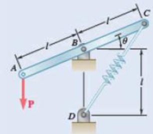
Fig. P10.37 and P10.38
Expert Solution & Answer
Want to see the full answer?
Check out a sample textbook solution
Students have asked these similar questions
Calculate the mean piston speed (in mph) for a Formula 1 engine running at 14,750 rpm with a bore of 80mm and a stroke of 53mm. Estimate the average acceleration imparted on the piston as it moves from TDC to 90 degrees ATDC
Calculate the compression ratio of an engine with a stroke of 4.2inches a bore of 4.5 inches and a clearance volume of 6.15 cubic inches. Discuss whether or not this is a realistic compression ratio for a street engine and what octane rating of fuel it would need to run correctly
Draw the free-body diagram for the pinned assembly shown. Find the magnitude of the forces
acting on each member of the assembly.
1500 N
1500 N
C
45°
45°
45°
45°
1000 mm
Chapter 10 Solutions
EBK VECTOR MECHANICS FOR ENGINEERS: STA
Ch. 10.1 - 10.1 Determine the vertical force P that must be...Ch. 10.1 - Determine the horizontal force P that must be...Ch. 10.1 - Prob. 10.3PCh. 10.1 - 10.3 and 10.4 Determine the couple M that must be...Ch. 10.1 - A spring of constant 15 kN/m connects points C and...Ch. 10.1 - A spring of constant 15 kN/m connects points C and...Ch. 10.1 - The two-bar linkage shown is supported by a pin...Ch. 10.1 - Prob. 10.8PCh. 10.1 - Prob. 10.9PCh. 10.1 - Prob. 10.10P
Ch. 10.1 - Prob. 10.11PCh. 10.1 - Knowing that the line of action of the force Q...Ch. 10.1 - Solve Prob. 10.12 assuming that the force P...Ch. 10.1 - Prob. 10.14PCh. 10.1 - Prob. 10.15PCh. 10.1 - Prob. 10.16PCh. 10.1 - A uniform rod AB with length l and weight W is...Ch. 10.1 - The pin at C is attached to member BCD and can...Ch. 10.1 - For the linkage shown, determine the couple M...Ch. 10.1 - For the linkage shown, determine the force...Ch. 10.1 - A 4-kN force P is applied as shown to the piston...Ch. 10.1 - A couple M with a magnitude of 100 Nm isapplied as...Ch. 10.1 - Rod AB is attached to a block at A that can...Ch. 10.1 - Solve Prob. 10.23, assuming that the 800-N force...Ch. 10.1 - Prob. 10.25PCh. 10.1 - Prob. 10.26PCh. 10.1 - Prob. 10.27PCh. 10.1 - Prob. 10.28PCh. 10.1 - Prob. 10.29PCh. 10.1 - Two rods AC and CE are connected by a pin at Cand...Ch. 10.1 - Solve Prob. 10.30 assuming that force P is movedto...Ch. 10.1 - Two bars AD and DG are connected by a pin at Dand...Ch. 10.1 - Solve Prob. 10.32 assuming that the 900-N...Ch. 10.1 - Two 5-kg bars AB and BC are connected by a pin atB...Ch. 10.1 - A vertical force P with a magnitude of 150 N...Ch. 10.1 - Prob. 10.36PCh. 10.1 - 10.37 and 10.38 Knowing that the constant of...Ch. 10.1 - Prob. 10.38PCh. 10.1 - The lever AB is attached to the horizontal shaft...Ch. 10.1 - Solve Prob. 10.39, assuming that P = 350 N, l =250...Ch. 10.1 - Prob. 10.41PCh. 10.1 - The position of boom ABC is controlled by...Ch. 10.1 - The position of member ABC is controlled by the...Ch. 10.1 - The position of member ABC is controlled by...Ch. 10.1 - The telescoping arm ABC is used to provide...Ch. 10.1 - Solve Prob. 10.45, assuming that the workers...Ch. 10.1 - Denoting the coefficient of static friction...Ch. 10.1 - Knowing that the coefficient of static...Ch. 10.1 - A block with weight W is pulled up a plane forming...Ch. 10.1 - Derive an expression for the mechanical...Ch. 10.1 - Denoting the coefficient of static friction...Ch. 10.1 - Knowing that the coefficient of static...Ch. 10.1 - Using the method of virtual work,...Ch. 10.1 - Using the method of virtual work, determine...Ch. 10.1 - Referring to Prob. 10.43 and using the value...Ch. 10.1 - Prob. 10.56PCh. 10.1 - Prob. 10.57PCh. 10.1 - Prob. 10.58PCh. 10.2 - Using the method of Sec. 10.2C, solve Prob. 10.29....Ch. 10.2 - Using the method of Sec. 10.2C, solve Prob. 10.30....Ch. 10.2 - Using the method of Sec. 10.2C, solve Prob. 10.31....Ch. 10.2 - Using the method of Sec. 10.2C, solve Prob. 10.32....Ch. 10.2 - Using the method of Sec. 10.2C, solve Prob. 10.34....Ch. 10.2 - Prob. 10.64PCh. 10.2 - Using the method of Sec. 10.2C, solve Prob. 10.37....Ch. 10.2 - Prob. 10.66PCh. 10.2 - Prob. 10.67PCh. 10.2 - Show that equilibrium is neutral in Prob. 10.7....Ch. 10.2 - Two uniform rods, each with a mass m, areattached...Ch. 10.2 - Two uniform rods, AB and CD, are attached to gears...Ch. 10.2 - Two uniform rods AB and CD, of the same length...Ch. 10.2 - Two uniform rods, each of mass m and length l, are...Ch. 10.2 - Using the method of Sec. 10.2C, solve Prob....Ch. 10.2 - In Prob. 10.40, determine whether each of...Ch. 10.2 - Prob. 10.75PCh. 10.2 - Prob. 10.76PCh. 10.2 - Prob. 10.77PCh. 10.2 - Prob. 10.78PCh. 10.2 - A slender rod AB with a weight W is attached to...Ch. 10.2 - A slender rod AB with a weight W is attached totwo...Ch. 10.2 - Prob. 10.81PCh. 10.2 - A spring AB of constant k is attached to two...Ch. 10.2 - A slender rod AB is attached to two collars A and...Ch. 10.2 - Prob. 10.84PCh. 10.2 - 10.85 and 10.86 Cart B, which weighs 75 kN, rolls...Ch. 10.2 - 10.85 and 10.86 Cart B, which weighs 75 kN, rolls...Ch. 10.2 - 10.87 and 10.88 Collar A can slide freely on the...Ch. 10.2 - 10.87 and 10.88 Collar A can slide freely on the...Ch. 10.2 - Prob. 10.89PCh. 10.2 - A vertical bar AD is attached to two springs...Ch. 10.2 - Rod AB is attached to a hinge at A and to two...Ch. 10.2 - Rod AB is attached to a hinge at A and to...Ch. 10.2 - Two bars are attached to a single spring of...Ch. 10.2 - Prob. 10.94PCh. 10.2 - The horizontal bar BEH is connected to three...Ch. 10.2 - The horizontal bar BEH is connected to three...Ch. 10.2 - Bars AB and BC, each with a length l and of...Ch. 10.2 - Prob. 10.98PCh. 10.2 - Prob. 10.99PCh. 10.2 - Prob. 10.100PCh. 10 - Determine the vertical force P that must be...Ch. 10 - Determine the couple M that must be applied...Ch. 10 - Determine the force P required to maintain...Ch. 10 - Derive an expression for the magnitude of the...Ch. 10 - Derive an expression for the magnitude of the...Ch. 10 - A vertical load W is applied to the linkage at B....Ch. 10 - A force P with a magnitude of 240 N is applied to...Ch. 10 - Two identical rods ABC and DBE are connected bya...Ch. 10 - Solve Prob. 10.108 assuming that the 24-lb load...Ch. 10 - Two uniform rods each with a mass m and length...Ch. 10 - A homogeneous hemisphere with a radius r isplaced...Ch. 10 - A homogeneous hemisphere with a radius r isplaced...
Knowledge Booster


Learn more about
Need a deep-dive on the concept behind this application? Look no further. Learn more about this topic, mechanical-engineering and related others by exploring similar questions and additional content below.Similar questions
- An elastic bar of length L spins with angular velocity ω about an axis, as shown in the figure below. The radial acceleration at a generic point x along the bar is a(x) = ω 2 x. Due to this radial acceleration, the bar stretches along x with displacement function u(x). The displacement u(x) is governed by the following equations: ( d dx (σ(x)) + ρa(x) = 0 PDE σ(x) = E du dx Hooke’s law (1) where σ(x) is the axial stress in the rod, ρ is the mass density, and E is the (constant) Young’s modulus. The bar is pinned on the rotation axis at x = 0, and it is free at x = L. Determine:1. Appropriate BCs for this physical problem.2. The displacement function u(x).3. The stress function σ(x).arrow_forwardWith reference to the given figure: a) Draw a free-body diagram of the structure supporting the pulley. b) Draw shear and bending moment diagrams for both the vertical and horizontal portions of the structure. 48 in. 100 lb 12 in. Cable 27 in. 12-in. pulley radius 100 lb Cablearrow_forwardConsider a standard piston engine . Draw a free body diagram of the piston. Then:a) For an A SI engine with a 100 mm bore at an instantaneous cylinder pressure of 42 bar i. Calculate the level of the combustion gas loading force on the wrist pin in kN. b) Repeat this calculationfor a forced-induction Diesel engine with a 145 mm boreat a cylinder pressure of 115 bararrow_forward
- A punch press with flywheel adequate to minimize speed fluctuation produces 120 punching strokes per minute, each providing an average force of 2000 N over a stroke of 50 mm. The press is driven through a gear reducer by a shaft rotating 200 rpm. Overall efficiency is 80%. a) What power (W) is transmitted through the shaft? b) What average torque is applied to the shaft?arrow_forward1.58 The crankshaft of a single-cylinder air compressor rotates 1800 rpm. The piston area is 2000 mm2 and the piston stroke is 50 mm. Assume a simple “idealized” case where the average gas pressure acting on the piston during the compression stroke is 1 MPa, and pressure during the intake stroke is negligible. The compressor is 80% efficient. A flywheel provides adequate control of the speed fluctuation. a) What motor power (kW) is required to drive the crankshaft? b) What torque is transmitted through the crankshaft?arrow_forward28. The shaft shown in Figure P5-28 is supported by bear- ings at each end, which have bores of 20.0 mm. Design the shaft to carry the given load if it is steady and the shaft is stationary. Make the dimension a as large as pos- sible while keeping the stress safe. Determine the required d 20 mm 5.4 kN d D = ? Length not to scale -α = = -125 mm 20 mm a = -250 mm- FIGURE P5-28 (Problems 28, 29, and 30)arrow_forward
- The motor shown operates at constant speed and develops a torque of 100 lb-in during normal operation. Attached to the motor shaft is a gear reducer of ratio 5:1, that is, the reducer output shaft rotates in the same direction as the motor but at one-fifth motor speed. Rotation of the reducer housing is prevented by the "torque arm" pin-connected at each end as shown. The reducer output shaft drives the load through a flexible coupling. Neglecting gravity and friction, what loads are applied to (a) the torque arm, (b) the motor output shaft, and (c) the reducer output shaft? Motor Gear reducer Flexible coupling (To load) Torque arm- Torque arm Reducer output shaft Motor Reducer Shaft rotationarrow_forwardPlease can you help with ten attatched question?arrow_forwardAn AISI 1018 steel ball with 1.100-in diameter is used as a roller between a flat plate made from 2024 T3 aluminum and a flat table surface made from ASTM No. 30 gray cast iron. Determine the maximum amount of weight that can be stacked on the aluminum plate without exceeding a maximum shear stress of 19.00 kpsi in any of the three pieces. Assume the figure given below, which is based on a typical Poisson's ratio of 0.3, is applicable to estimate the depth at which the maximum shear stress occurs for these materials. 1.0 0.8 Ratio of stress to Pmax 0.4 90 0.6 στ Tmax 0.2 0.5a a 1.5a 2a 2.5a За Distance from contact surface The maximum amount of weight that can be stacked on the aluminum plate is lbf.arrow_forward
- A carbon steel ball with 27.00-mm diameter is pressed together with an aluminum ball with a 36.00-mm diameter by a force of 11.00 N. Determine the maximum shear stress and the depth at which it will occur for the aluminum ball. Assume the figure given below, which is based on a typical Poisson's ratio of 0.3, is applicable to estimate the depth at which the maximum shear stress occurs for these materials. 1.0 0.8 Ratio of stress to Pma 9 0.6 στ 24 0.4 Tmax 0.2 0 0.5a a 1.5a Z 2a 2.5a За Distance from contact surface The maximum shear stress is determined to be MPa. The depth in the aluminum ball at which the maximum shear stress will occur is determined to be [ mm.arrow_forwardShow all work pleasearrow_forwardDraw top, side, front view With pen(cil) and paper Multi view drawing and handwriting all of itarrow_forward
arrow_back_ios
SEE MORE QUESTIONS
arrow_forward_ios
Recommended textbooks for you
 International Edition---engineering Mechanics: St...Mechanical EngineeringISBN:9781305501607Author:Andrew Pytel And Jaan KiusalaasPublisher:CENGAGE L
International Edition---engineering Mechanics: St...
Mechanical Engineering
ISBN:9781305501607
Author:Andrew Pytel And Jaan Kiusalaas
Publisher:CENGAGE L
Introduction to Undamped Free Vibration of SDOF (1/2) - Structural Dynamics; Author: structurefree;https://www.youtube.com/watch?v=BkgzEdDlU78;License: Standard Youtube License