
EBK VECTOR MECHANICS FOR ENGINEERS: STA
11th Edition
ISBN: 8220102809888
Author: BEER
Publisher: YUZU
expand_more
expand_more
format_list_bulleted
Videos
Textbook Question
Chapter 10.1, Problem 10.42P
The position of boom ABC is controlled by the hydraulic cylinder BD. For the loading shown, determine the largest allowable value of the angle θ if the maximum force that the cylinder can exert on pin B is 25 kips.
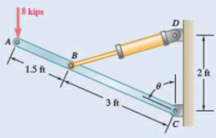
Fig. P10.41 and P10.42
Expert Solution & Answer
Want to see the full answer?
Check out a sample textbook solution
Students have asked these similar questions
Please can you help with ten attatched question?
An AISI 1018 steel ball with 1.100-in diameter is used as a roller between a flat plate
made from 2024 T3 aluminum and a flat table surface made from ASTM No. 30 gray
cast iron. Determine the maximum amount of weight that can be stacked on the
aluminum plate without exceeding a maximum shear stress of 19.00 kpsi in any of the
three pieces. Assume the figure given below, which is based on a typical Poisson's
ratio of 0.3, is applicable to estimate the depth at which the maximum shear stress
occurs for these materials.
1.0
0.8
Ratio of stress to Pmax
0.4
90
0.6
στ
Tmax
0.2
0.5a
a
1.5a
2a
2.5a
За
Distance from contact surface
The maximum amount of weight that can be stacked on the aluminum plate is
lbf.
A carbon steel ball with 27.00-mm diameter is pressed together with an aluminum ball
with a 36.00-mm diameter by a force of 11.00 N. Determine the maximum shear
stress and the depth at which it will occur for the aluminum ball. Assume the figure
given below, which is based on a typical Poisson's ratio of 0.3, is applicable to estimate
the depth at which the maximum shear stress occurs for these materials.
1.0
0.8
Ratio of stress to Pma
9 0.6
στ
24
0.4
Tmax
0.2
0
0.5a
a
1.5a
Z
2a
2.5a
За
Distance from contact surface
The maximum shear stress is determined to be
MPa.
The depth in the aluminum ball at which the maximum shear stress will occur is
determined to be [
mm.
Chapter 10 Solutions
EBK VECTOR MECHANICS FOR ENGINEERS: STA
Ch. 10.1 - 10.1 Determine the vertical force P that must be...Ch. 10.1 - Determine the horizontal force P that must be...Ch. 10.1 - Prob. 10.3PCh. 10.1 - 10.3 and 10.4 Determine the couple M that must be...Ch. 10.1 - A spring of constant 15 kN/m connects points C and...Ch. 10.1 - A spring of constant 15 kN/m connects points C and...Ch. 10.1 - The two-bar linkage shown is supported by a pin...Ch. 10.1 - Prob. 10.8PCh. 10.1 - Prob. 10.9PCh. 10.1 - Prob. 10.10P
Ch. 10.1 - Prob. 10.11PCh. 10.1 - Knowing that the line of action of the force Q...Ch. 10.1 - Solve Prob. 10.12 assuming that the force P...Ch. 10.1 - Prob. 10.14PCh. 10.1 - Prob. 10.15PCh. 10.1 - Prob. 10.16PCh. 10.1 - A uniform rod AB with length l and weight W is...Ch. 10.1 - The pin at C is attached to member BCD and can...Ch. 10.1 - For the linkage shown, determine the couple M...Ch. 10.1 - For the linkage shown, determine the force...Ch. 10.1 - A 4-kN force P is applied as shown to the piston...Ch. 10.1 - A couple M with a magnitude of 100 Nm isapplied as...Ch. 10.1 - Rod AB is attached to a block at A that can...Ch. 10.1 - Solve Prob. 10.23, assuming that the 800-N force...Ch. 10.1 - Prob. 10.25PCh. 10.1 - Prob. 10.26PCh. 10.1 - Prob. 10.27PCh. 10.1 - Prob. 10.28PCh. 10.1 - Prob. 10.29PCh. 10.1 - Two rods AC and CE are connected by a pin at Cand...Ch. 10.1 - Solve Prob. 10.30 assuming that force P is movedto...Ch. 10.1 - Two bars AD and DG are connected by a pin at Dand...Ch. 10.1 - Solve Prob. 10.32 assuming that the 900-N...Ch. 10.1 - Two 5-kg bars AB and BC are connected by a pin atB...Ch. 10.1 - A vertical force P with a magnitude of 150 N...Ch. 10.1 - Prob. 10.36PCh. 10.1 - 10.37 and 10.38 Knowing that the constant of...Ch. 10.1 - Prob. 10.38PCh. 10.1 - The lever AB is attached to the horizontal shaft...Ch. 10.1 - Solve Prob. 10.39, assuming that P = 350 N, l =250...Ch. 10.1 - Prob. 10.41PCh. 10.1 - The position of boom ABC is controlled by...Ch. 10.1 - The position of member ABC is controlled by the...Ch. 10.1 - The position of member ABC is controlled by...Ch. 10.1 - The telescoping arm ABC is used to provide...Ch. 10.1 - Solve Prob. 10.45, assuming that the workers...Ch. 10.1 - Denoting the coefficient of static friction...Ch. 10.1 - Knowing that the coefficient of static...Ch. 10.1 - A block with weight W is pulled up a plane forming...Ch. 10.1 - Derive an expression for the mechanical...Ch. 10.1 - Denoting the coefficient of static friction...Ch. 10.1 - Knowing that the coefficient of static...Ch. 10.1 - Using the method of virtual work,...Ch. 10.1 - Using the method of virtual work, determine...Ch. 10.1 - Referring to Prob. 10.43 and using the value...Ch. 10.1 - Prob. 10.56PCh. 10.1 - Prob. 10.57PCh. 10.1 - Prob. 10.58PCh. 10.2 - Using the method of Sec. 10.2C, solve Prob. 10.29....Ch. 10.2 - Using the method of Sec. 10.2C, solve Prob. 10.30....Ch. 10.2 - Using the method of Sec. 10.2C, solve Prob. 10.31....Ch. 10.2 - Using the method of Sec. 10.2C, solve Prob. 10.32....Ch. 10.2 - Using the method of Sec. 10.2C, solve Prob. 10.34....Ch. 10.2 - Prob. 10.64PCh. 10.2 - Using the method of Sec. 10.2C, solve Prob. 10.37....Ch. 10.2 - Prob. 10.66PCh. 10.2 - Prob. 10.67PCh. 10.2 - Show that equilibrium is neutral in Prob. 10.7....Ch. 10.2 - Two uniform rods, each with a mass m, areattached...Ch. 10.2 - Two uniform rods, AB and CD, are attached to gears...Ch. 10.2 - Two uniform rods AB and CD, of the same length...Ch. 10.2 - Two uniform rods, each of mass m and length l, are...Ch. 10.2 - Using the method of Sec. 10.2C, solve Prob....Ch. 10.2 - In Prob. 10.40, determine whether each of...Ch. 10.2 - Prob. 10.75PCh. 10.2 - Prob. 10.76PCh. 10.2 - Prob. 10.77PCh. 10.2 - Prob. 10.78PCh. 10.2 - A slender rod AB with a weight W is attached to...Ch. 10.2 - A slender rod AB with a weight W is attached totwo...Ch. 10.2 - Prob. 10.81PCh. 10.2 - A spring AB of constant k is attached to two...Ch. 10.2 - A slender rod AB is attached to two collars A and...Ch. 10.2 - Prob. 10.84PCh. 10.2 - 10.85 and 10.86 Cart B, which weighs 75 kN, rolls...Ch. 10.2 - 10.85 and 10.86 Cart B, which weighs 75 kN, rolls...Ch. 10.2 - 10.87 and 10.88 Collar A can slide freely on the...Ch. 10.2 - 10.87 and 10.88 Collar A can slide freely on the...Ch. 10.2 - Prob. 10.89PCh. 10.2 - A vertical bar AD is attached to two springs...Ch. 10.2 - Rod AB is attached to a hinge at A and to two...Ch. 10.2 - Rod AB is attached to a hinge at A and to...Ch. 10.2 - Two bars are attached to a single spring of...Ch. 10.2 - Prob. 10.94PCh. 10.2 - The horizontal bar BEH is connected to three...Ch. 10.2 - The horizontal bar BEH is connected to three...Ch. 10.2 - Bars AB and BC, each with a length l and of...Ch. 10.2 - Prob. 10.98PCh. 10.2 - Prob. 10.99PCh. 10.2 - Prob. 10.100PCh. 10 - Determine the vertical force P that must be...Ch. 10 - Determine the couple M that must be applied...Ch. 10 - Determine the force P required to maintain...Ch. 10 - Derive an expression for the magnitude of the...Ch. 10 - Derive an expression for the magnitude of the...Ch. 10 - A vertical load W is applied to the linkage at B....Ch. 10 - A force P with a magnitude of 240 N is applied to...Ch. 10 - Two identical rods ABC and DBE are connected bya...Ch. 10 - Solve Prob. 10.108 assuming that the 24-lb load...Ch. 10 - Two uniform rods each with a mass m and length...Ch. 10 - A homogeneous hemisphere with a radius r isplaced...Ch. 10 - A homogeneous hemisphere with a radius r isplaced...
Knowledge Booster


Learn more about
Need a deep-dive on the concept behind this application? Look no further. Learn more about this topic, mechanical-engineering and related others by exploring similar questions and additional content below.Similar questions
- Show all work pleasearrow_forwardDraw top, side, front view With pen(cil) and paper Multi view drawing and handwriting all of itarrow_forwardA wheel of diameter 150.0 mm and width 37.00 mm carrying a load 2.200 kN rolls on a flat rail. Take the wheel material as steel and the rail material as cast iron. Assume the figure given, which is based on a Poisson's ratio of 0.3, is applicable to estimate the depth at which the maximum shear stress occurs for these materials. At this critical depth, calculate the Hertzian stresses σr, σy, σz, and Tmax for the wheel. 1.0 0.8 0, т Ratio of stress to Pmax 0.4 0.6 90 69 0.2 0.5b b 1.5b Tmax 2b Distance from contact surface The Hertizian stresses are as follows: 02 = or = -23.8 psi for the wheel =| necessary.) σy for the wheel =| MPa σz for the wheel = MPa V4 for the wheel = | MPa 2.5b ཡི 3b MPa (Include a minus sign ifarrow_forward
- 4. Solve for the support reactions at A and B. W1 600 lb/ft W2 150 lb/ft A Barrow_forwardIn cold isostatic pressing, the mold is most typically made of which one of the following: thermosetting polymer tool steel sheet metal textile rubberarrow_forwardThe coefficient of friction between the part and the tool in cold working tends to be: lower higher no different relative to its value in hot workingarrow_forward
- The force F={25i−45j+15k}F={25i−45j+15k} lblb acts at the end A of the pipe assembly shown in (Figure 1). Determine the magnitude of the component F1 which acts along the member AB. Determine the magnitude of the component F2 which acts perpendicular to the AB.arrow_forwardHi can you please help me with the attached question?arrow_forwardHi can you please help me with the attached question?arrow_forward
arrow_back_ios
SEE MORE QUESTIONS
arrow_forward_ios
Recommended textbooks for you
 Elements Of ElectromagneticsMechanical EngineeringISBN:9780190698614Author:Sadiku, Matthew N. O.Publisher:Oxford University Press
 Mechanics of Materials (10th Edition)Mechanical EngineeringISBN:9780134319650Author:Russell C. HibbelerPublisher:PEARSON
 Thermodynamics: An Engineering ApproachMechanical EngineeringISBN:9781259822674Author:Yunus A. Cengel Dr., Michael A. BolesPublisher:McGraw-Hill Education
 Control Systems EngineeringMechanical EngineeringISBN:9781118170519Author:Norman S. NisePublisher:WILEY
 Mechanics of Materials (MindTap Course List)Mechanical EngineeringISBN:9781337093347Author:Barry J. Goodno, James M. GerePublisher:Cengage Learning
 Engineering Mechanics: StaticsMechanical EngineeringISBN:9781118807330Author:James L. Meriam, L. G. Kraige, J. N. BoltonPublisher:WILEY
Elements Of Electromagnetics
Mechanical Engineering
ISBN:9780190698614
Author:Sadiku, Matthew N. O.
Publisher:Oxford University Press
Mechanics of Materials (10th Edition)
Mechanical Engineering
ISBN:9780134319650
Author:Russell C. Hibbeler
Publisher:PEARSON
Thermodynamics: An Engineering Approach
Mechanical Engineering
ISBN:9781259822674
Author:Yunus A. Cengel Dr., Michael A. Boles
Publisher:McGraw-Hill Education
Control Systems Engineering
Mechanical Engineering
ISBN:9781118170519
Author:Norman S. Nise
Publisher:WILEY
Mechanics of Materials (MindTap Course List)
Mechanical Engineering
ISBN:9781337093347
Author:Barry J. Goodno, James M. Gere
Publisher:Cengage Learning
Engineering Mechanics: Statics
Mechanical Engineering
ISBN:9781118807330
Author:James L. Meriam, L. G. Kraige, J. N. Bolton
Publisher:WILEY
How to balance a see saw using moments example problem; Author: Engineer4Free;https://www.youtube.com/watch?v=d7tX37j-iHU;License: Standard Youtube License