
Concept explainers
Videos
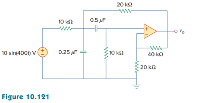
Determine vo(t) in the op amp circuit in Fig. 10.121 below.
Calculate the output voltage
Answer to Problem 78P
The value of output voltage
Explanation of Solution
Given data:
Refer to Figure 10.121 in the textbook for op amp circuit.
Formula used:
Write the expression to calculate impedance of the capacitor.
Here,
Write the general representation of sinusoidal sine function.
Here,
Write the general expression to phasor transform of sinusoidal function from time domain to frequency domain.
Here,
Write the polar form representation of frequency domain.
Calculation:
Comparing
Substitute
Substitute
Substitute
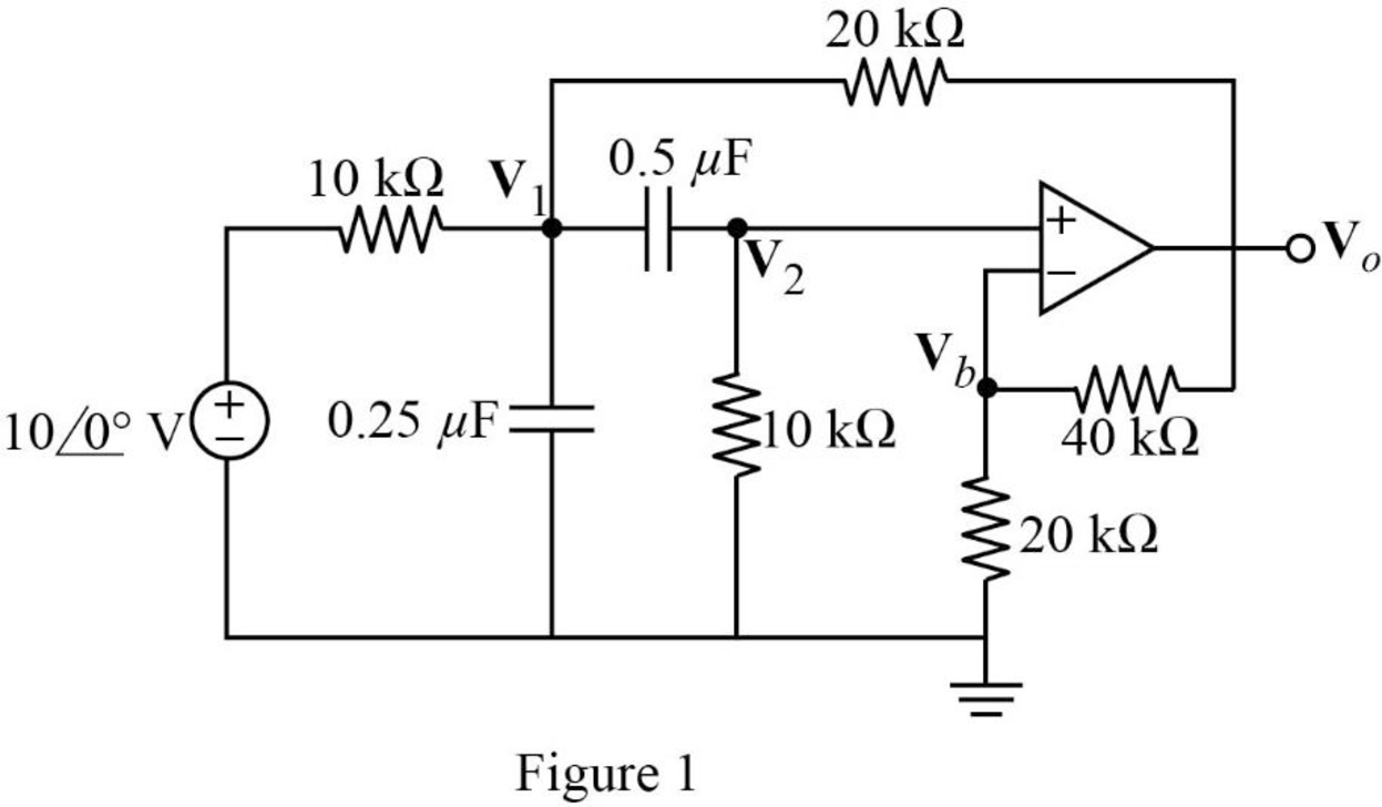
The frequency domain representation of given figure is shown in Figure 1.
Apply Kirchhoff’s current law at node
Simplify the equation as follows.
Apply Kirchhoff’s current law at node
Apply voltage division rule at node
According to the properties of ideal op amp, the voltage at the input of the non-inverting terminal of the op amp is equal to the voltage at the input of the inverting terminal. Hence,
Substitute equation (5) in (1).
Substitute equation (5) in (2).
Represent the equations (6) and (7) in matrix form.
Write the MATLAB code to solve equation (8) to find
A = [3+6*1i -1-1.333*1i; 1 -0.3333+0.1666*1i];
b = [20; 0];
x = A\b
The MATLAB result is shown below.
x =
5.9463 - 4.3272i 19.4666 - 3.2525i
The polar representation of obtained result is shown below.
Represent the output voltage in time domain.
Conclusion:
Thus, the value of output voltage
Want to see more full solutions like this?
Chapter 10 Solutions
EBK FUNDAMENTALS OF ELECTRIC CIRCUITS


- 12.12 In the circuit of Fig. P12.12(a), is(t) is given by the waveform shown in Fig. P12.12(b). Determine iL (t) for t≥ 0, given that R₁ = R₂ = 2 2 and L = 4 H. is() R₁ R2: (a) Circuit is(t) 8A- 8e-21 elle (b) is(t) Figure P12.12 Circuit and waveform for Problem 12.12. iLarrow_forward12.12 In the circuit of Fig. P12.12(a), is(t) is given by thewaveform shown in Fig. P12.12(b). Determine iL(t) for t ≥ 0,given that R1 = R2 = 2 W and L = 4 H.arrow_forward12.4 Determine the Laplace transform of each of the following functions by applying the properties given in Tables 12-1 and 12-2 on pages 642-643. (a) fi(t)=4tet u(t) (b) f2(t)=10cos (12t+60°) u(t) *(c) f3(t) = 12e−3(t−4) u(t −4) (d) f4(t) = 30(e³ +e³t) u(t) (e) fs(t)=16e2t cos 4t u(t) (f) f6(t)=20te 2 sin 4t u(t)arrow_forward
- a) Calculate the values of v and i. + 803 1A Va 82 b) Determine the power dissipated in each resistor. 1A Va (a) + I 50 V 0.2 S (b) + D + 1 Α υ€ 20 Ω 50 V 250 ΩΣ ia (c) (d) Copyright ©2015 Pearson Education, All Rights Reservedarrow_forwardExercise 3-12: Find the Thévenin equivalent of the circuit to the left of terminals (a, b) in Fig. E3.12, and then determine the current I. 502 502 0.6 Ω 20 V | + <302 Ω ΣΙΩ b 2025 Ω 15A Figure E3.12arrow_forward2. Consider following feedback system. r(t) e(t) y(t) K G(s) 1 where G(S) = s²+as+b In above, K, a and b are constants. Select the values of K, a and b in a way so that (i) (ii) (iii) the closed loop system is stable, steady-state error of the closed-loop system for step input is 0.2, the closed-loop response has 20% overshoot and 2 seconds as settling time.arrow_forward
- 4. Answer the following questions. Take help from ChatGPT to answer these questions (if you need). But write the answers briefly using your own words with no more than two sentences, and make sure you check whether ChatGPT is giving you the appropriate answers in the context of class. a) What is the advantage of the PI controller over the proportional controller? b) What is the advantage of the PD controller over a proportional controller? c) In the presence of noise, what problem do we face implementing the derivate part of the PID (or PD) controller? To address this, what do we usually use? d) What are the forms of lead compensator and lag compensator? How do these two types of compensators differ?arrow_forward3. Consider the following closed-loop system as shown in the figure. 16 Ge(s) s(s + 4) Suppose Ge(s) is a PID controller with Kp = 1, KD = 2 and K₁ = 3. a) Find the controller transfer function G₁(s). b) Find the open-loop transfer function. c) Find the closed-loop transfer function.arrow_forwardExercise 3-12: Find the Thévenin equivalent of the circuit to the left of terminals (a, b) in Fig. E3.12, and then determine the current I. 502 5 Ω 0.6 Ω a 3Ω ΣΙΩ b 20 V 1 + 2027 15A Figure E3.12arrow_forward
- solve and show workarrow_forwardDon't use ai to answer I will report you answerarrow_forwardvalues. 4. Discussion: DEPA الأمهريائية RING Compare between theoretic bination effect of Kp and KI at first order and second order systems regarding steady-state errors and transient responses with the practical. In Experiment PI Controllerarrow_forward
 Delmar's Standard Textbook Of ElectricityElectrical EngineeringISBN:9781337900348Author:Stephen L. HermanPublisher:Cengage Learning