Videos
Review. An object with a mass of m = 5.10 kg is attached to the free end of a light string wrapped around a reel of radius R = 0.250 m and mass M = 3.00 kg. The reel is a solid disk, free to rotate in a vertical plane about the horizontal axis passing through its center as shown in Figure P10.45. The suspended object is released from rest 6.00 m above the floor. Determine
- (a) the tension in the string,
- (b) the acceleration of the object, and
- (c) the speed with which the object hits the floor.
- (d) Verify your answer to part (c) by using the isolated system (energy) model.
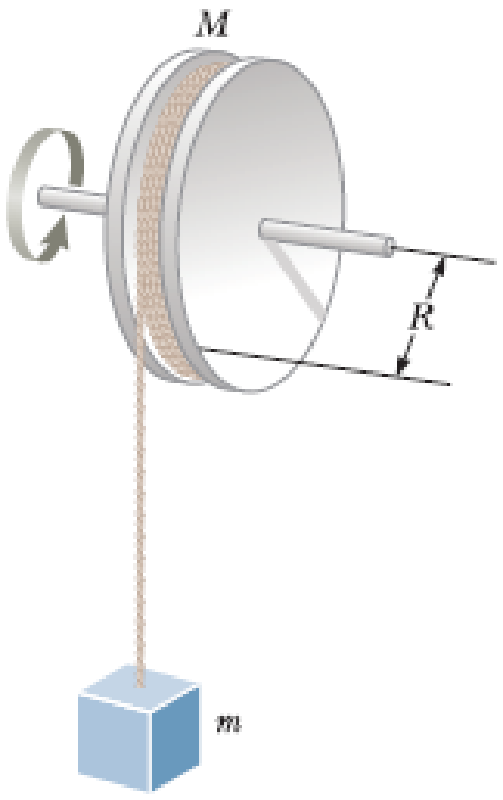
Figure P10.45
(a)
The tension acting on the string.
Answer to Problem 45P
The tension acting on the string is
Explanation of Solution
Consider the figure given below.
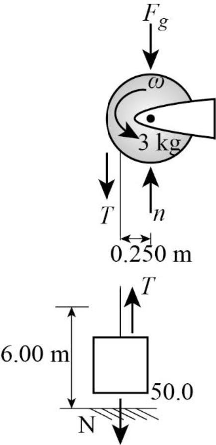
The forces acting on the reel are given in the figure 1. The gravitational force acting on the reel is
Write the expression for the gravitational force.
Here,
The reel can be considered as a uniform disk, let
Write the expression for the moment of inertia of the reel.
Here,
Write the expression for torque about the axis of rotation.
Here,
Equate
Here,
Substitute,
Write the expression of force in downward direction.
Conclusion:
Substitute,
Substitute,
Substitute,
Substitute,
Substitute, equation (VII) in equation (VIII) to obtain the value of acceleration.
Substitute,
Therefore, the tension acting on the string is
(b)
The acceleration of the object.
Answer to Problem 45P
The acceleration of the object is
Explanation of Solution
The acceleration is already calculated in part (a).
Conclusion:
Therefore, the acceleration of the object is
(c)
The speed with which object hits the ground.
Answer to Problem 45P
The speed with which object hits the ground is
Explanation of Solution
Write the Newton’s equation of motion for the final velocity.
Here,
Conclusion:
Substitute,
Therefore, the speed with which object hits the ground is
(d)
To verify the value of speed of the object using isolated system model.
Answer to Problem 45P
The value of acceleration obtained using both methods are same.
Explanation of Solution
Write the equation for the conservation energy in case of the given system.
Here,
Substitute,
Substitute,
Conclusion:
Substitute,
Therefore, the value of acceleration obtained using both methods are same.
Want to see more full solutions like this?
Chapter 10 Solutions
Bundle: Principles of Physics: A Calculus-Based Text, 5th + WebAssign Printed Access Card for Serway/Jewett's Principles of Physics: A Calculus-Based Text, 5th Edition, Multi-Term


- Kirchoff's Laws. A circuit contains 3 known resistors, 2 known batteries, and 3 unknown currents as shown. Assume the current flows through the circuit as shown (this is our initial guess, the actual currents may be reverse). Use the sign convention that a potential drop is negative and a potential gain is positive. E₂ = 8V R₁₁ = 50 R₂ = 80 b с w 11 www 12 13 E₁ = 6V R3 = 20 a) Apply Kirchoff's Loop Rule around loop abefa in the clockwise direction starting at point a. (2 pt). b) Apply Kirchoff's Loop Rule around loop bcdeb in the clockwise direction starting at point b. (2 pt). c) Apply Kirchoff's Junction Rule at junction b (1 pt). d) Solve the above 3 equations for the unknown currents I1, 12, and 13 and specify the direction of the current around each loop. (5 pts) I1 = A 12 = A 13 = A Direction of current around loop abef Direction of current around loop bcde (CW or CCW) (CW or CCW)arrow_forwardNo chatgpt pls will upvotearrow_forward4.) The diagram shows the electric field lines of a positively charged conducting sphere of radius R and charge Q. A B Points A and B are located on the same field line. A proton is placed at A and released from rest. The magnitude of the work done by the electric field in moving the proton from A to B is 1.7×10⁻¹⁶ J. Point A is at a distance of 5.0×10⁻²m from the centre of the sphere. Point B is at a distance of 1.0×10⁻¹ m from the centre of the sphere. (a) Explain why the electric potential decreases from A to B. [2] (b) Draw, on the axes, the variation of electric potential V with distance r from the centre of the sphere. R [2] (c(i)) Calculate the electric potential difference between points A and B. [1] (c(ii)) Determine the charge Q of the sphere. [2] (d) The concept of potential is also used in the context of gravitational fields. Suggest why scientists developed a common terminology to describe different types of fields. [1]arrow_forward
- 3.) The graph shows how current I varies with potential difference V across a component X. 904 80- 70- 60- 50- I/MA 40- 30- 20- 10- 0+ 0 0.5 1.0 1.5 2.0 2.5 3.0 3.5 4.0 4.5 5.0 VIV Component X and a cell of negligible internal resistance are placed in a circuit. A variable resistor R is connected in series with component X. The ammeter reads 20mA. 4.0V 4.0V Component X and the cell are now placed in a potential divider circuit. (a) Outline why component X is considered non-ohmic. [1] (b(i)) Determine the resistance of the variable resistor. [3] (b(ii)) Calculate the power dissipated in the circuit. [1] (c(i)) State the range of current that the ammeter can measure as the slider S of the potential divider is moved from Q to P. [1] (c(ii)) Describe, by reference to your answer for (c)(i), the advantage of the potential divider arrangement over the arrangement in (b).arrow_forward1.) Two long parallel current-carrying wires P and Q are separated by 0.10 m. The current in wire P is 5.0 A. The magnetic force on a length of 0.50 m of wire P due to the current in wire Q is 2.0 × 10-s N. (a) State and explain the magnitude of the force on a length of 0.50 m of wire Q due to the current in P. [2] (b) Calculate the current in wire Q. [2] (c) Another current-carrying wire R is placed parallel to wires P and Q and halfway between them as shown. wire P wire R wire Q 0.05 m 0.05 m The net magnetic force on wire Q is now zero. (c.i) State the direction of the current in R, relative to the current in P.[1] (c.ii) Deduce the current in R. [2]arrow_forward2.) A 50.0 resistor is connected to a cell of emf 3.00 V. The voltmeter and the ammeter in the circuit are ideal. V A 50.00 (a) The current in the ammeter is 59.0 mA. Calculate the internal resistance of the cell. The circuit is changed by connecting another resistor R in parallel to the 50.0 resistor. V A 50.00 R (b) Explain the effect of this change on R is made of a resistive wire of uniform cross-sectional area 3.1 × 10⁻⁸ m², resistivity 4.9 × 10-70m and length L. The resistance of R is given by the equation R = KL where k is a constant. (b.i) the reading of the ammeter. [2] (b.ii) the reading of the voltmeter. [2] (c) Calculate k. State an appropriate unit for your answer. [3] [2]arrow_forward
- No chatgpt pls will upvotearrow_forwardNo chatgpt pls will upvotearrow_forwardA rod 12.0 cm long is uniformly charged and has a total charge of -20.0 μc. Determine the magnitude and direction of the electric field along the axis of the rod at a point 32.0 cm from its center. 361000 ☑ magnitude What is the general expression for the electric field along the axis of a uniform rod? N/C direction toward the rodarrow_forward
 Principles of Physics: A Calculus-Based TextPhysicsISBN:9781133104261Author:Raymond A. Serway, John W. JewettPublisher:Cengage Learning
 Physics for Scientists and Engineers: Foundations...PhysicsISBN:9781133939146Author:Katz, Debora M.Publisher:Cengage Learning
 Physics for Scientists and EngineersPhysicsISBN:9781337553278Author:Raymond A. Serway, John W. JewettPublisher:Cengage Learning
 Physics for Scientists and Engineers with Modern ...PhysicsISBN:9781337553292Author:Raymond A. Serway, John W. JewettPublisher:Cengage Learning
 College PhysicsPhysicsISBN:9781305952300Author:Raymond A. Serway, Chris VuillePublisher:Cengage Learning
 Physics for Scientists and Engineers, Technology ...PhysicsISBN:9781305116399Author:Raymond A. Serway, John W. JewettPublisher:Cengage Learning