(II) A potter is shaping a bowl on a potter’s wheel rotating at constant angular speed (Fig. 10–51). The friction force between her hands and the clay is 1.5 N total. ( a ) How large is her torque on the wheel, if the diameter of the howl is 12 cm? ( b ) How long would it take for the potter’s wheel to stop if the only torque acting on it is due to the potter’s hand? The initial angular velocity of the wheel is 1.6 rev/s, and the moment of inertia of the wheel and the howl is 0.11 kg · m 2 .
(II) A potter is shaping a bowl on a potter’s wheel rotating at constant angular speed (Fig. 10–51). The friction force between her hands and the clay is 1.5 N total. ( a ) How large is her torque on the wheel, if the diameter of the howl is 12 cm? ( b ) How long would it take for the potter’s wheel to stop if the only torque acting on it is due to the potter’s hand? The initial angular velocity of the wheel is 1.6 rev/s, and the moment of inertia of the wheel and the howl is 0.11 kg · m 2 .
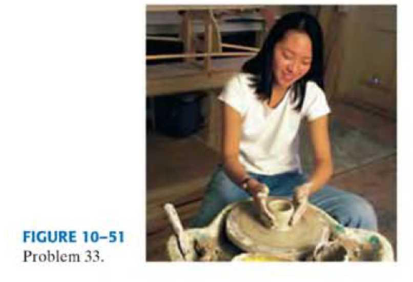
(II) A potter is shaping a bowl on a potter’s wheel rotating at constant angular speed (Fig. 10–51). The friction force between her hands and the clay is 1.5 N total. (a) How large is her torque on the wheel, if the diameter of the howl is 12 cm? (b) How long would it take for the potter’s wheel to stop if the only torque acting on it is due to the potter’s hand? The initial angular velocity of the wheel is 1.6 rev/s, and the moment of inertia of the wheel and the howl is 0.11 kg · m2.
Definition Definition Rate of change of angular velocity. Angular acceleration indicates how fast the angular velocity changes over time. It is a vector quantity and has both magnitude and direction. Magnitude is represented by the length of the vector and direction is represented by the right-hand thumb rule. An angular acceleration vector will be always perpendicular to the plane of rotation. Angular acceleration is generally denoted by the Greek letter α and its SI unit is rad/s 2 .
4.) The diagram shows the electric field lines of a positively charged conducting sphere of
radius R and charge Q.
A
B
Points A and B are located on the same field line.
A proton is placed at A and released from rest. The magnitude of the work done by the electric field in
moving the proton from A to B is 1.7×10⁻¹⁶ J. Point A is at a distance of 5.0×10⁻²m from the centre of
the sphere. Point B is at a distance of 1.0×10⁻¹ m from the centre of the sphere.
(a) Explain why the electric potential decreases from A to B. [2]
(b) Draw, on the axes, the variation of electric potential V with distance r from the centre of the
sphere.
R
[2]
(c(i)) Calculate the electric potential difference between points A and B. [1]
(c(ii)) Determine the charge Q of the sphere. [2]
(d) The concept of potential is also used in the context of gravitational fields. Suggest why scientists
developed a common terminology to describe different types of fields. [1]
3.) The graph shows how current I varies with potential difference V across a component X.
904
80-
70-
60-
50-
I/MA
40-
30-
20-
10-
0+
0
0.5
1.0 1.5 2.0 2.5 3.0 3.5 4.0 4.5 5.0
VIV
Component X and a cell of negligible internal resistance are placed in a circuit.
A variable resistor R is connected in series with component X. The ammeter reads 20mA.
4.0V
4.0V
Component X and the cell are now placed in a potential divider circuit.
(a) Outline why component X is considered non-ohmic. [1]
(b(i)) Determine the resistance of the variable resistor. [3]
(b(ii)) Calculate the power dissipated in the circuit. [1]
(c(i)) State the range of current that the ammeter can measure as the slider S of the potential divider
is moved from Q to P. [1]
(c(ii)) Describe, by reference to your answer for (c)(i), the advantage of the potential divider
arrangement over the arrangement in (b).
1.) Two long parallel current-carrying wires P and Q are separated by 0.10 m. The current in wire P is 5.0 A.
The magnetic force on a length of 0.50 m of wire P due to the current in wire Q is 2.0 × 10-s N.
(a) State and explain the magnitude of the force on a length of 0.50 m of wire Q due to the current in P. [2]
(b) Calculate the current in wire Q. [2]
(c) Another current-carrying wire R is placed parallel to wires P and Q and halfway between them as shown.
wire P
wire R
wire Q
0.05 m
0.05 m
The net magnetic force on wire Q is now zero.
(c.i) State the direction of the current in R, relative to the current in P.[1]
(c.ii) Deduce the current in R. [2]
Chapter 10 Solutions
Physics for Science and Engineering With Modern Physics, VI - Student Study Guide
Need a deep-dive on the concept behind this application? Look no further. Learn more about this topic, physics and related others by exploring similar questions and additional content below.


 University Physics Volume 1PhysicsISBN:9781938168277Author:William Moebs, Samuel J. Ling, Jeff SannyPublisher:OpenStax - Rice University
 Glencoe Physics: Principles and Problems, Student...PhysicsISBN:9780078807213Author:Paul W. ZitzewitzPublisher:Glencoe/McGraw-Hill
 Principles of Physics: A Calculus-Based TextPhysicsISBN:9781133104261Author:Raymond A. Serway, John W. JewettPublisher:Cengage Learning
 College PhysicsPhysicsISBN:9781938168000Author:Paul Peter Urone, Roger HinrichsPublisher:OpenStax College
 Physics for Scientists and Engineers: Foundations...PhysicsISBN:9781133939146Author:Katz, Debora M.Publisher:Cengage Learning
 College PhysicsPhysicsISBN:9781305952300Author:Raymond A. Serway, Chris VuillePublisher:Cengage Learning