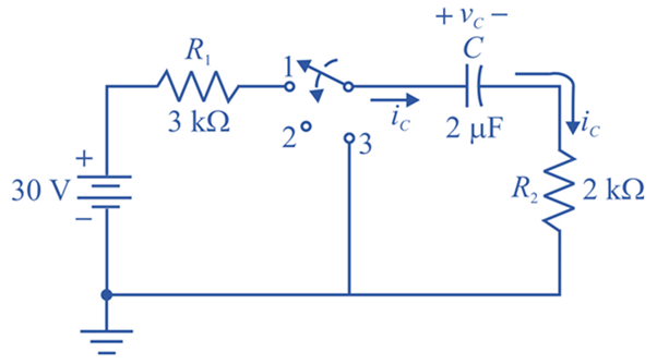
For the network in Fig. 10.98. composed of standard values:
a. Write the mathematical expressions for the voltages Uc. and vR1 and the current ic after the switch is thrown into position 1.
b. Find the values of vc, vR1. and ic when the switch is moved to position 2 at t = 100 ms.
c. Write the mathematical expressions for the voltages Uc and ic and VR2 the current ic if the switch is moved to position 3 at
d. Plot the waveforms of vc,vR2 and ic for the time period extending from 0 to 300 ms.

Fig. 10.98
Trending nowThis is a popular solution!

Chapter 10 Solutions
Introductory Circuit Analysis (13th Edition)
Additional Engineering Textbook Solutions
Mechanics of Materials (10th Edition)
Starting Out with Programming Logic and Design (5th Edition) (What's New in Computer Science)
SURVEY OF OPERATING SYSTEMS
BASIC BIOMECHANICS
Database Concepts (8th Edition)
Java: An Introduction to Problem Solving and Programming (8th Edition)
- What is the high cutoff frequency? What is the low cutoff frequency? What is the bandwidth?arrow_forwardNeed handwritten pen and paper solution do not use chatgpt or AI otherwise downvote. An AC motor with impedance Z₁ = 4.2 + j3.6 ohm is supplied from a source of 220 V at 60 Hz. Find: a) pf, P and Q, b) Determine the capacitor required to connect in parallel with the motor so that the power factor is corrected and equal to 0.98 behind.arrow_forwardNeed handwritten pen and paper solution do not use chatgpt or AI otherwise downvote An AC motor with impedance Z₁ = 4.2 + j3.6 ohm is supplied from a source of 220 V at 60 Hz. Find: a) pf, P and Q, b) Determine the capacitor required to connect in parallel with the motor so that the power factor is corrected and equal to 0.98 behind.arrow_forward
- (b) Below is a FSM with a 1-bit input A, and a 1-bit output Y. Deter- mine the combined state and output table. Identify the unreachable states, and sketch the state-transition diagram. In your table and diagram, use Os and 1s for the states and next states, not symbols like S0, S1, etc. A D D D CLK S'₁₂ S2 S₁₁ S1 Y S' r So S2 S₁ So resetarrow_forwardDo by pen and paper not using chatgpt Determine the output current of E1 in the circuit shown in . The voltage drop of the diodes is 0.7 V.arrow_forwardDon't use ai to answer I will report you answerarrow_forward
- For the amplifier shown, if β = 150: Calculate the input impedance at the base. Calculate the input impedance of the stage.arrow_forward53. Obtain an expression for i(t) as labeled in the circuit diagram of Fig. 8.84, and determine the power being dissipated in the 40 2 resistor at t = 2.5 ms. t=0 i(t) 30 Ω w 200 mA 4002 30 m 100 mA(arrow_forward7.2 At t = 0, the switch in the circuit shown moves instantaneously from position a to position b. a) Calculate v, for t≥ 0. b) What percentage of the initial energy stored in the inductor is eventually dissipated in the 4 resistor? 6Ω a w + 10 0.32 H3 403 6.4 A =0 b Answer: (a) -8e-10 V, t = 0; (b) 80%.arrow_forward
 Power System Analysis and Design (MindTap Course ...Electrical EngineeringISBN:9781305632134Author:J. Duncan Glover, Thomas Overbye, Mulukutla S. SarmaPublisher:Cengage Learning
