
Introductory Circuit Analysis (13th Edition)
13th Edition
ISBN: 9780133923605
Author: Robert L. Boylestad
Publisher: PEARSON
expand_more
expand_more
format_list_bulleted
Videos
Textbook Question
Chapter 10, Problem 44P
The capacitors in Fig. 10.112 are initially charged to 12 V with the polarity shown.
a. Write the mathematical expressions for the voltage UC and the current iC when the switch is closed.
b. Sketch the waveforms of UC and iC
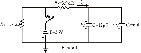
Fig. 10.112
Expert Solution & Answer
Want to see the full answer?
Check out a sample textbook solution
Students have asked these similar questions
A17)
Using Carson's rule, determine the transmission bandwidth for commercial FM radio broadcasting, provided that the maximum value of frequency deviation is 75 kHz and the bandwidth of the audio signal is 15 kHz
2. Laboratory Preliminary Discussion
First-order High-pass RC Filter Analysis
The first-order high-pass RC filter shown in figure 3 below represents all voltages and currents in the time domain. We will again
convert the circuit to its s-domain equivalent as shown in figure 4 and apply Laplace transform techniques.
ic(t)
C
vs(t)
i₁(t)
+
+
vc(t)
R1
ww
Vi(t)
|| 12(t)
V2(t)
R₂
Vout(t) VR2(t) = V2(t)
Figure 3: A first-order high-pass RC filter represented in the time domain.
Ic(s)
C
+
Vs(s)
I₁(s)
+
+
Vc(s)
R₁
www
V₁(s)
12(s)
V₂(s)
R₂
Vout(S)
=
VR2(S)
= V2(s)
Figure 4: A first-order high-pass RC filter represented in the s-domain.
Again, to generate the s-domain expression for the output voltage, You (S) = V2 (s), for the circuit shown in figure 4 above, we can
apply voltage division in the s-domain as shown in equation 2 below. Equation 2 will be used in the prelab computations to find
an expression for the output voltage, xc(t), in the time domain.
equation (2)
R₂
Vout(s) = V₂(s) =
R₂+…
Chapter 10 Solutions
Introductory Circuit Analysis (13th Edition)
Ch. 10 - a. Find the electric field strength at a point 1 m...Ch. 10 - The electric field strength is 72 newtons/coulomb...Ch. 10 - Find the capacitance of a parallel plate capacitor...Ch. 10 - How much charge is deposited on the plates of a...Ch. 10 - a. Find the electric field strength between the...Ch. 10 - A 6.8 pF parallel plate capacitor has 160 C of...Ch. 10 - Find the capacitance of a parallel plate capacitor...Ch. 10 - Repeat Problem 7 if the dielectric is...Ch. 10 - Find the distance in mils between the plates of a...Ch. 10 - The capacitance of a capacitor with a dielectric...
Ch. 10 - The plates of a parallel plate capacitor with a...Ch. 10 - A parallel plate air capacitor has a capacitance...Ch. 10 - Find the maximum voltage that can be applied...Ch. 10 - Find the distance in micrometers between the...Ch. 10 - A 22 pF capacitor has -200 ppm/C at room...Ch. 10 - What is the capacitance of a small teardrop...Ch. 10 - A large, flat, mica capacitor is labeled 471F....Ch. 10 - A small, flat, disc ceramic capacitor is labeled...Ch. 10 - For the circuit in Fig. 10.94, composed of...Ch. 10 - Repeat Problem 19 for R=100k, and compare the...Ch. 10 - For the circuit in Fig. 10.95, composed of...Ch. 10 - For the circuit in Fig. 10.96, composed of...Ch. 10 - Prob. 23PCh. 10 - The voltage across a 10 F capacitor in a series...Ch. 10 - For the R-C circuit in Fig. 10.97. composed of...Ch. 10 - For the network in Fig. 10.98. composed of...Ch. 10 - For the network in Fig.10.99.composed of standard...Ch. 10 - The 1000 F capacitor in Fig.10.100 is charged to...Ch. 10 - The capacitor in Fig. 10.101 is initially charged...Ch. 10 - Repeat Problem 29 if the initial charge is -40V.Ch. 10 - Repeat Problem 29 if the initial charge is +40V.Ch. 10 - The capacitor in Fig. 10.102 is initially charged...Ch. 10 - The capacitor in Fig. 10.103 is initially charged...Ch. 10 - The capacitor in Fig. 10.104 is initially charged...Ch. 10 - The capacitors of Fig. 10.105 are initially...Ch. 10 - Repeat Problem 35 if a 10 k resistor is placed in...Ch. 10 - Given the expression vc=140mV(1-e-t/2ms) a....Ch. 10 - For the automobile circuit of Fig. 10.106. VL must...Ch. 10 - Design the network in Fig.10.107 such that the...Ch. 10 - For the circuit in Fig. 10.108: a. Find the time...Ch. 10 - For the system in Fig. 10.109. using a DMM with a...Ch. 10 - For the circuit in Fig. 10.110: a. Find the...Ch. 10 - The capacitor in Fig. 10.111 is initially charged...Ch. 10 - The capacitors in Fig. 10.112 are initially...Ch. 10 - For the circuit in Fig. 10.113: a. Find the...Ch. 10 - The capacitor in Fig. 10.114 is initially charged...Ch. 10 - For the system in Fig. 10.115, using a DMM with a...Ch. 10 - Find the waveform for the average current if the...Ch. 10 - Find the waveform for the average current if the...Ch. 10 - Given the waveform in Fig.10.118 for the current...Ch. 10 - Find the total capacitance CT for the network in...Ch. 10 - Find the total capacitance CT for the network in...Ch. 10 - Find the steady-state voltage across and the...Ch. 10 - Find the steady-state voltage across and the...Ch. 10 - For the configuration in Fig. 10.123, determine...Ch. 10 - For the configuration in Fig.10.124, determine the...Ch. 10 - Find the energy stored by a 120 pF capacitor with...Ch. 10 - If the energy stored by a 6 F capacitor is 1200 J,...Ch. 10 - For the network in Fig. 10.125, determine the...Ch. 10 - An electronic flashgun has a 1000 F capacitor that...Ch. 10 - Using PSpice or Multisim, verify the results in...Ch. 10 - Using the initial condition operator, verify the...Ch. 10 - Using PSpice or Multisim, verify the results for...Ch. 10 - Using PSpice or Multisim, verify the results in...
Knowledge Booster


Learn more about
Need a deep-dive on the concept behind this application? Look no further. Learn more about this topic, electrical-engineering and related others by exploring similar questions and additional content below.Similar questions
- Can you show me the steps to get the last part after the second equal sign.arrow_forwardPrelab Information 1. Laboratory Preliminary Discussion First-order Low-pass RC Filter Analysis The first-order low-pass RC filter shown in figure 1 below represents all voltages and currents in the time domain. It is of course possible to solve for all circuit voltages using time domain differential equation techniques, but it is more efficient to convert the circuit to its s-domain equivalent as shown in figure 2 and apply Laplace transform techniques. vs(t) i₁(t) + R₁ ww V₁(t) 12(t) Lic(t) Vout(t) = V2(t) R₂ Vc(t) C Vc(t) VR2(t) = V2(t) + Vs(s) Figure 1: A first-order low-pass RC filter represented in the time domain. I₁(s) R1 W + V₁(s) V₂(s) 12(s) Ic(s) + Vout(S) == Vc(s) Vc(s) Zc(s) = = VR2(S) V2(s) Figure 2: A first-order low-pass RC filter represented in the s-domain.arrow_forwardA.15 Consider a communication channel, transfer characteristic of which is defined by the nonlinear relation, y(t) = x(t) + x² (t), where x(t) is the input and y(t) is the output. Assuming the input is an FM signal, x(t) = cos (2лft+(t)), find y(t). Is it possible to retrieve x(t) from y(t)? If so, how?arrow_forward
- 1) Show that a regenerative receiver can be used to recover message from the following modulated signals. a. DSB-PC b. DSB-SC 1b) Does the receiver need to recover the carrier phase? 1c) What are the filtering requirements and restrictions on message signal bandwidth and carrier frequency.arrow_forward2) Estimate the transmission bandwidth for the following FM modulated signals (W is the message bandwidth) a) W1KHz and frequency deviation of 75KHz b) W = 20KHz and frequency deviation of 75KHz c) W1KHz and frequency deviation of 150KHz d) W20KHz and frequency deviation of 150KHZarrow_forwardI want to explain how the result becomes (735.1) Hz) and what are the steps and explain the reasons? Q6 The FET shown in Fig. 1.43 has gm = 3.4mS and ra =100 K. Find the approximate lower cutoff frequency. Ans: 735.1 Hz. 25V 2ΚΩ 1.5ΜΩ 0.02µF 0.02µF 20 ΚΩ 330kQ 820 ΩΣ OpF Fig. 1.43 Circuit for Q6. 40ΚΩarrow_forward
- 3. What is the function of LM565 pin 6? 4. What is the purpose of the multistage low-pass filter between the LM565 output and the comparator input? C10.1μ FSK Input w₁ R2 100k -o+5V(Vcc) VR1 10k C4 C5: 0.1 μ. 0.1μ 0.1 μ 8 10 R3 R4 D₁ FSK Phase Rx 7 10K 10K Detector www ww ww 1N4004 + Demodulated Output 6 AMP R₁ 6 100k 3 C₂ 0.05 μ VCO 4 5 9 U1 -5V LM565 -0-5V(VEE) Fig. 14-2 FSK demodulator U2 R6 μ4741 10karrow_forward1. What components determine the free-running frequency of the VCO in LM565 of Fig. 14-2? 2. What is the purpose of μA741 in Fig. 14-2? C10.1μ FSK Input -o+5V(Vcc) VR1 10k C4 C5: 0.1 μ. 0.1 μ 0.1 μ 8 10 R3 R4 R5 Phase Rx 7 10K 10K 10k D₁ FSK Detector www ww ww ww 1N4004 + Demodulated Output AMP 6 R₁ 6 100k w₁ R2 100k 3 C₂ 0.05 μ VCO 4 5 9 U1 -5V LM565 -0-5V(VEE) Fig. 14-2 FSK demodulator U2 R6 μ4741 10karrow_forwardWhen troubleshooting power and control circuits, approximate meter readings should be anticipated if the meter readings are going to be used to help determine circuit problems. Determine the expected DMM reading if the ciircuit is working properly. The expected reading of DMM 1 with the motor on is what VAC? And the expected reading of DMM 2 with the motor is on is what VAC? And The expected reading of DMM 3 with the motor on is What mA?arrow_forward
- DU 1. Describe the operations of Q1, Q2 and LM566. 2. Describe the functions of VR1 and VR2. R6 lk R3 BRUD 3. If the input frequency is higher than the FSK frequency, does the FSK modulator operate normally? 0+12V R10 5.6k 6 10k VRI 500k U₁ LM566 3 VCO output 7 Digital input R₁ VR2 10k ww 1k Qi C945 C945 C5 I 0.1 uF C6 luF C₁ 0.01μ R2 10k ww R$ 100k C3 +12V 0.01μ R9 100k +12V 6 R710k Rs 100k 6 R4 100k P FSK output ww ww + www + 3 3 4 U U₂ 1000p -12V HA741 1000p-12V µА741 Fig. 13-2 FSK modulator CTS circuit.arrow_forward. 30-dB, right-circularly polarized antenna in a radio link radiates 5-W of power t 2 GHz. The input impedance of this antenna is 75 ohms, and it is attached ɔ a 50-ohm transmission line. The receiving antenna has an impedance mismatch at its terminals, - which leads to a VSWR of 2. The receiving antenna is about 95% efficient and has a field pattern near the beam maximum given by E, = (2âx + jây) F, (0, 0). The distance between the two antennas is 4,000 km, and the receiving antenna Directivity is 100. Determine the Minimum power Delivered to receiving antenna. 1arrow_forwardOpen plc - ladder logic To control traffic, we have red lights to stop cars and green lights to initiate entry/exit. If a car is in the lane, then the red lights turn ON. If no cars are in the lane, then the green lights turn ON. Upon turning ON the main switch button, the main switch indicator should turn ON and the system should start with green lights ON and red lights OFF?arrow_forward
arrow_back_ios
SEE MORE QUESTIONS
arrow_forward_ios
Recommended textbooks for you
 Introductory Circuit Analysis (13th Edition)Electrical EngineeringISBN:9780133923605Author:Robert L. BoylestadPublisher:PEARSON
 Delmar's Standard Textbook Of ElectricityElectrical EngineeringISBN:9781337900348Author:Stephen L. HermanPublisher:Cengage Learning
 Programmable Logic ControllersElectrical EngineeringISBN:9780073373843Author:Frank D. PetruzellaPublisher:McGraw-Hill Education
 Fundamentals of Electric CircuitsElectrical EngineeringISBN:9780078028229Author:Charles K Alexander, Matthew SadikuPublisher:McGraw-Hill Education
 Electric Circuits. (11th Edition)Electrical EngineeringISBN:9780134746968Author:James W. Nilsson, Susan RiedelPublisher:PEARSON
 Engineering ElectromagneticsElectrical EngineeringISBN:9780078028151Author:Hayt, William H. (william Hart), Jr, BUCK, John A.Publisher:Mcgraw-hill Education,
Introductory Circuit Analysis (13th Edition)
Electrical Engineering
ISBN:9780133923605
Author:Robert L. Boylestad
Publisher:PEARSON
Delmar's Standard Textbook Of Electricity
Electrical Engineering
ISBN:9781337900348
Author:Stephen L. Herman
Publisher:Cengage Learning
Programmable Logic Controllers
Electrical Engineering
ISBN:9780073373843
Author:Frank D. Petruzella
Publisher:McGraw-Hill Education
Fundamentals of Electric Circuits
Electrical Engineering
ISBN:9780078028229
Author:Charles K Alexander, Matthew Sadiku
Publisher:McGraw-Hill Education
Electric Circuits. (11th Edition)
Electrical Engineering
ISBN:9780134746968
Author:James W. Nilsson, Susan Riedel
Publisher:PEARSON
Engineering Electromagnetics
Electrical Engineering
ISBN:9780078028151
Author:Hayt, William H. (william Hart), Jr, BUCK, John A.
Publisher:Mcgraw-hill Education,
Inductors Explained - The basics how inductors work working principle; Author: The Engineering Mindset;https://www.youtube.com/watch?v=KSylo01n5FY;License: Standard Youtube License