
Introductory Circuit Analysis (13th Edition)
13th Edition
ISBN: 9780133923605
Author: Robert L. Boylestad
Publisher: PEARSON
expand_more
expand_more
format_list_bulleted
Videos
Textbook Question
Chapter 10, Problem 46P
The capacitor in Fig. 10.114 is initially charged to 8 V with the polarity shown.
a. Write the mathematical expressions for the voltage UC and the current iC when the switch is closed.
b. Sketch the waveforms of UC and iC.
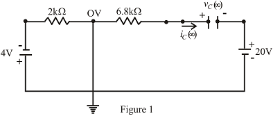
Fig.10.114
Expert Solution & Answer
Want to see the full answer?
Check out a sample textbook solution
Students have asked these similar questions
1. For the circuit shown, let Is = 10, R₁-45, R2-5, R3-5, and R4-45, to find:
(choose the closest value in volts) (V)
{NOTE: On Multiple Choice Questions, like this problem, you have only one attempt }
• Vab
50
(V)
-25
225
R₁
a
R2
RA
b
R3
Vab
power systems
Find G(s) = Vs(s) / Ve(s) for this circuit below
Chapter 10 Solutions
Introductory Circuit Analysis (13th Edition)
Ch. 10 - a. Find the electric field strength at a point 1 m...Ch. 10 - The electric field strength is 72 newtons/coulomb...Ch. 10 - Find the capacitance of a parallel plate capacitor...Ch. 10 - How much charge is deposited on the plates of a...Ch. 10 - a. Find the electric field strength between the...Ch. 10 - A 6.8 pF parallel plate capacitor has 160 C of...Ch. 10 - Find the capacitance of a parallel plate capacitor...Ch. 10 - Repeat Problem 7 if the dielectric is...Ch. 10 - Find the distance in mils between the plates of a...Ch. 10 - The capacitance of a capacitor with a dielectric...
Ch. 10 - The plates of a parallel plate capacitor with a...Ch. 10 - A parallel plate air capacitor has a capacitance...Ch. 10 - Find the maximum voltage that can be applied...Ch. 10 - Find the distance in micrometers between the...Ch. 10 - A 22 pF capacitor has -200 ppm/C at room...Ch. 10 - What is the capacitance of a small teardrop...Ch. 10 - A large, flat, mica capacitor is labeled 471F....Ch. 10 - A small, flat, disc ceramic capacitor is labeled...Ch. 10 - For the circuit in Fig. 10.94, composed of...Ch. 10 - Repeat Problem 19 for R=100k, and compare the...Ch. 10 - For the circuit in Fig. 10.95, composed of...Ch. 10 - For the circuit in Fig. 10.96, composed of...Ch. 10 - Prob. 23PCh. 10 - The voltage across a 10 F capacitor in a series...Ch. 10 - For the R-C circuit in Fig. 10.97. composed of...Ch. 10 - For the network in Fig. 10.98. composed of...Ch. 10 - For the network in Fig.10.99.composed of standard...Ch. 10 - The 1000 F capacitor in Fig.10.100 is charged to...Ch. 10 - The capacitor in Fig. 10.101 is initially charged...Ch. 10 - Repeat Problem 29 if the initial charge is -40V.Ch. 10 - Repeat Problem 29 if the initial charge is +40V.Ch. 10 - The capacitor in Fig. 10.102 is initially charged...Ch. 10 - The capacitor in Fig. 10.103 is initially charged...Ch. 10 - The capacitor in Fig. 10.104 is initially charged...Ch. 10 - The capacitors of Fig. 10.105 are initially...Ch. 10 - Repeat Problem 35 if a 10 k resistor is placed in...Ch. 10 - Given the expression vc=140mV(1-e-t/2ms) a....Ch. 10 - For the automobile circuit of Fig. 10.106. VL must...Ch. 10 - Design the network in Fig.10.107 such that the...Ch. 10 - For the circuit in Fig. 10.108: a. Find the time...Ch. 10 - For the system in Fig. 10.109. using a DMM with a...Ch. 10 - For the circuit in Fig. 10.110: a. Find the...Ch. 10 - The capacitor in Fig. 10.111 is initially charged...Ch. 10 - The capacitors in Fig. 10.112 are initially...Ch. 10 - For the circuit in Fig. 10.113: a. Find the...Ch. 10 - The capacitor in Fig. 10.114 is initially charged...Ch. 10 - For the system in Fig. 10.115, using a DMM with a...Ch. 10 - Find the waveform for the average current if the...Ch. 10 - Find the waveform for the average current if the...Ch. 10 - Given the waveform in Fig.10.118 for the current...Ch. 10 - Find the total capacitance CT for the network in...Ch. 10 - Find the total capacitance CT for the network in...Ch. 10 - Find the steady-state voltage across and the...Ch. 10 - Find the steady-state voltage across and the...Ch. 10 - For the configuration in Fig. 10.123, determine...Ch. 10 - For the configuration in Fig.10.124, determine the...Ch. 10 - Find the energy stored by a 120 pF capacitor with...Ch. 10 - If the energy stored by a 6 F capacitor is 1200 J,...Ch. 10 - For the network in Fig. 10.125, determine the...Ch. 10 - An electronic flashgun has a 1000 F capacitor that...Ch. 10 - Using PSpice or Multisim, verify the results in...Ch. 10 - Using the initial condition operator, verify the...Ch. 10 - Using PSpice or Multisim, verify the results for...Ch. 10 - Using PSpice or Multisim, verify the results in...
Knowledge Booster


Learn more about
Need a deep-dive on the concept behind this application? Look no further. Learn more about this topic, electrical-engineering and related others by exploring similar questions and additional content below.Similar questions
- Calculate the magnitude of the current in the coils e1, e2 of the magnetic circuit, if: ɸa = 3,00 x 10⁻³ Wb, φb = 0,80 x 10⁻³ Wb, ɸc = 2,20 x 10⁻³ Wb L AB = 0,10 m, L AFEB = L ACDB = 0,40 m AAB = 5,0 cm2 A AFEB = A ACDB = 20 cm2 Material characteristics H (At/m) 240 350 530 1300 5000 9000 B (T) 0,7 0,9 1,1 1,3 1,5 1,6arrow_forwardPower systemsarrow_forwardExplain the advantages and disadvantages of using silicon (Si) anode versus graphitic anode (C6) and write charging reactions for these anodes. Explain the effect of increasing state of charge window (SOC) of lithium battery and how SOC-window impact energy density and cycle life of the battery.arrow_forward
- Don't use guidelines okk just solve all accurate only 100% sure experts solve it correct complete solutions okkkarrow_forward3. Consider the circuit, in which R₁ = 10 KQ2, R2 = 5 KQ, R3 = 1 KQ, and RE = 8 KQ. The supply voltages are +Vcc = 10 V and -VEE = -5 V. Other parameters are ẞF = 100, VBE(On) = 0.7 V, and VCE(Sat) 0.2 V. Rc value will be specified later. (a) (3 points) Draw the dc equivalent circuit of the circuit. VI +Vcc Rc R2 RI R₁ RE -VEE υο R3 (b) Find the Thevenin equivalent voltage source VEQ and input resistance REQ of the DC equivalent circuit. Show your work. +Vcc Rc UC VEQ www REQ VE VEQ = REQ = ΚΩ RE VEEarrow_forward5. Consider the ac equivalent circuit of an amplifier, where RE = 1 KS2, gm = 0.05 S, and Υπ= 2Κ Ω. (a) Redraw the ac equivalent circuit using the hybrid-pi small signal model for BJTS. Include ro in the model. R₁ ww Vi RB ww + RL Vo RE (b) Find the terminal resistance RIB using the circuit obtained in (a). Ignore ro. Show your work. (Don't use formula for RiB.)arrow_forward
- 4. Consider the circuit. Use the symbol || to indicate the parallel of resistors in the following questions. (a) Express the input resistance Rin in terms of the terminal resistance and other necessary resistor values. (In other words, RiB, Ric, and RIE are given.) C₁ R₁ R₂ +Vcc Rc C3 R3 C2 ی RE -VEE (b) Express the output resistance Rout in terms of the terminal resistance and other necessary resistor values. (In other words, RiB, Ric and RiE are given.) (c) Express the voltage gain A₁ = ∞ in terms of terminal voltage gain Avt, the terminal Vi resistance, and other necessary resistor values. (Avt, RiB, Ric and R₁E are given.) +51arrow_forward2. ẞ 100, VBE(on)= 0.7 V, and VCE(sat) = 0.2 V for the BJT. We want to find the Q-point through the following steps. Show your work. a) Find the bias voltage VTH Using Thevenin's equivalent circuit. R1|| R2 www +5 V R₁ = 20 k IB VTH Answer: VTH = V b) Find the base current voltage IB. www. Answer: IB = μA (note the unit.) c) Find the collector voltage Vc (with reference to the ground). RC= 2.3 k B E R₂ = 30 k -5 V www R₁ = 5 ΚΩ ww AHI› RE= 5 ΚΩarrow_forward3. Consider the circuit, in which R₁ = 10 KQ2, R2 = 5 KQ, R3 = 1 KQ, and RE = 8 KQ. The supply voltages are +Vcc = 10 V and -VEE = -5 V. Other parameters are ẞF = 100, VBE(On) = 0.7 V, and VCE(Sat) 0.2 V. Rc value will be specified later. (a) (3 points) Draw the dc equivalent circuit of the circuit. VI +Vcc Rc R2 RI R₁ RE -VEE υο R3 (b) Find the Thevenin equivalent voltage source VEQ and input resistance REQ of the DC equivalent circuit. Show your work. +Vcc Rc UC VEQ www REQ VE VEQ = REQ = ΚΩ RE VEEarrow_forward
arrow_back_ios
SEE MORE QUESTIONS
arrow_forward_ios
Recommended textbooks for you
 Delmar's Standard Textbook Of ElectricityElectrical EngineeringISBN:9781337900348Author:Stephen L. HermanPublisher:Cengage Learning
Delmar's Standard Textbook Of Electricity
Electrical Engineering
ISBN:9781337900348
Author:Stephen L. Herman
Publisher:Cengage Learning
Inductors Explained - The basics how inductors work working principle; Author: The Engineering Mindset;https://www.youtube.com/watch?v=KSylo01n5FY;License: Standard Youtube License