
Electric Motor Control
10th Edition
ISBN: 9781133702818
Author: Herman
Publisher: CENGAGE L
expand_more
expand_more
format_list_bulleted
Videos
Textbook Question
Chapter 10, Problem 10SQ
Refer to Figure 10–6. When the thermostat contact closes, the compressor and evaporator fan start but the condenser fan does not start. Which of the following could NOT cause this problem?
a. The condenser fan motor is burned out.
b. The coil of the CF contactor is open.
c. One of the CF load contacts is defective.
d. The CFOL contact is open.
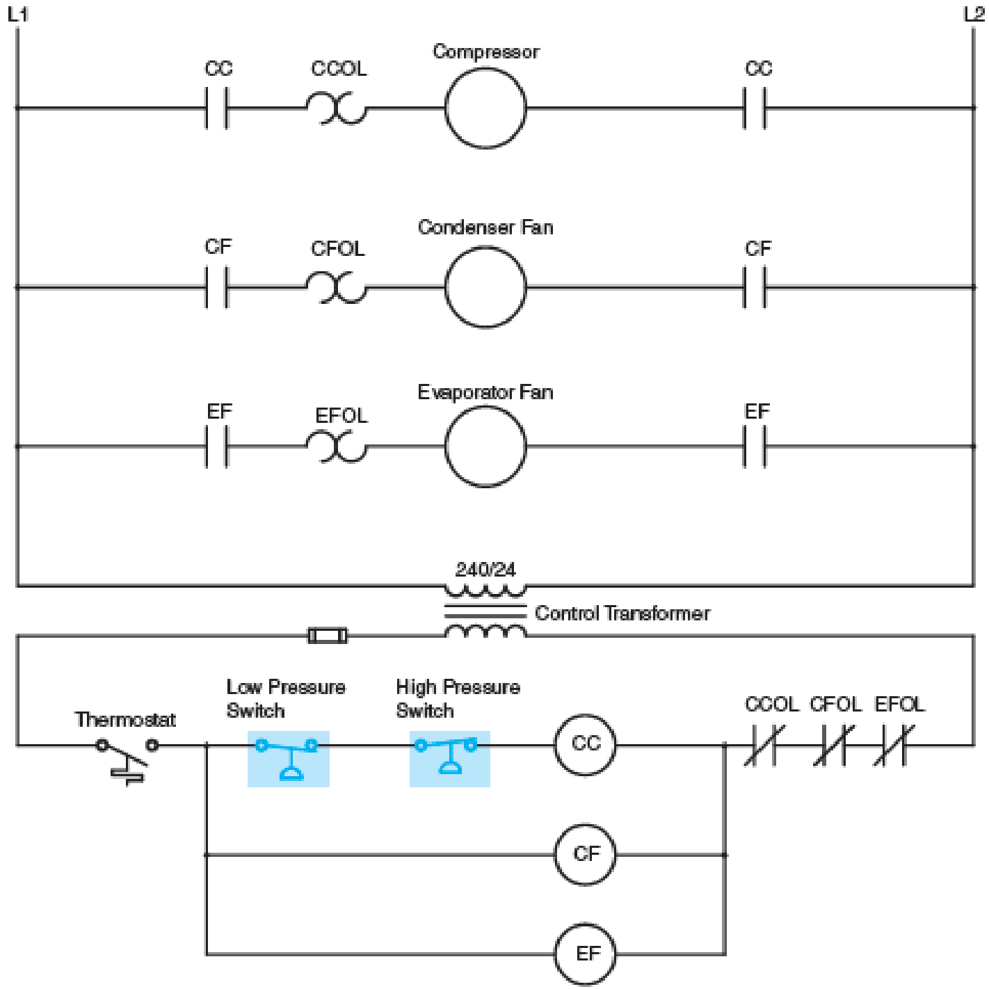
Fig. 10–6 Pressure switches are often used in air-conditioning circuits.
Expert Solution & Answer
Want to see the full answer?
Check out a sample textbook solution
Students have asked these similar questions
Calculate the neutral current in a 208Y/120-volt, 3-phase, 4-wire system when the current in phase A is 20, in phase B is 40, and in phase C is 60 amperes. The load is resistive.
I need expert to solve this,if you don't know don't attempt,also show the signal flow diagram
Pls show neat and whole solution
Chapter 10 Solutions
Electric Motor Control
Ch. 10 - Describe how pressure switches are connected to...Ch. 10 - What type of pressure switch is generally used to...Ch. 10 - A pressure switch is set to cut in at a pressure...Ch. 10 - A pressure switch is to be installed on a system...Ch. 10 - A pressure switch is to be installed in a circuit...Ch. 10 - Refer to the circuit shown in Figure 105. If the...Ch. 10 - Refer to the circuit shown in Figure 105. Assume...Ch. 10 - Refer to the circuit shown in Figure 106. Assume...Ch. 10 - Refer to the circuit shown in Figure 106. Assume...Ch. 10 - Refer to Figure 106. When the thermostat contact...
Knowledge Booster


Learn more about
Need a deep-dive on the concept behind this application? Look no further. Learn more about this topic, electrical-engineering and related others by exploring similar questions and additional content below.Similar questions
- Pls show neat and whole solution.arrow_forward. (35pts) For the circuit given below, let [VBE] = 0.7 V and ẞ=co. Find I, V1, V2, V3, V4, and V5. R-12 Kiloohms 6 Qz R2-3 kilo onnis +27V es -2.7V R₂arrow_forward1) A circuit is given as shown. (a) Find and label the circuit nodes. (6) Determine I, II, I₂ and V, I mm 22 +1 m 50 4 12 12v 2 ти + V ≤1652 50 mv Ми 60arrow_forward
- HANDWRITTEN SOLUTION NOT USING CHATGPT PLEASEarrow_forwardDesign a full-wave rectifier power supply using a 9.52:1 transformer. Assume that the outlet is120 V rms @ 60 Hz. Further assume that the diode turn-on voltage V D(on) is 0.7 V. Pick the valueof CL such that vo has a maximum ripple of 1 V p-p . Solve for the average value of vo = Vo (notethat this may be greater than 12 V) and iD(ave) = ID.arrow_forwardLight-emitting diodes (LEDs) are diodes made with III-V compound semiconductor materials such as aluminum gallium arsenide (AlGaAs), aluminum indium gallium phosphide (AlInGaP) or indium gallium nitride (InGaN), instead of silicon. The LEDs emit light when the device is operated under forward bias. LEDs of different colors have different turn-on voltages VD(on). For example: VD(on) : Red: ~ 1.6 V Yellow: ~ 1.7 V Green: ~ 1.8 V Blue: ~ 2.8 V White: ~ 3.8 V (a) Model these five LEDs with a simplified piecewise linear model (b) A rule of thumb is that it takes about 1 mA of current to “light” an LED while ~ 10 mA is needed for it to appear bright. Use the piecewise linear model for the LEDs, for the over-voltage indicator circuit to the right, find the values of Vin which will cause D1 or D2 to light (i.e. when ID1 or ID2 exceeds 1 mA).arrow_forward
- Consider a fixed and updated instrumentation amplifier (where two resistors are lumped into one resistor), analyze the circuit if a common voltage source (VICM) is connected to two inputs. A₁ R₂ + R₁ R₂, RA www www R₁ R₁ www A3 X R₁ R₂ www www R₁₂ + Vo RA A2 V2 O- + R₂ 12 R₁arrow_forwardShow that the input impedance of a lossy transmission line of length L connected to a load impedance of Z is given by Z₁Cosh(yL) + ZoSinh(yL) Zin = Zo ZoCosh(YL) + Z₁Sihh(YL) ex Where Cosh(x) = and Sinh(x) = are the hyperbolic cosine and sine, respectively. 2 2arrow_forwardA sinusoidal source of V = 10 and Z = 50 - j40 is connected to a 60 lossless transmission line of length 100 m with ẞ = 0.25. What is the Thevenin's equivalent of this system seen looking into the load end of the transmission line?arrow_forward
arrow_back_ios
SEE MORE QUESTIONS
arrow_forward_ios
Recommended textbooks for you
 Power System Analysis and Design (MindTap Course ...Electrical EngineeringISBN:9781305632134Author:J. Duncan Glover, Thomas Overbye, Mulukutla S. SarmaPublisher:Cengage Learning
Power System Analysis and Design (MindTap Course ...
Electrical Engineering
ISBN:9781305632134
Author:J. Duncan Glover, Thomas Overbye, Mulukutla S. Sarma
Publisher:Cengage Learning
Pressure Sensors with Display; Author: Balluff Worldwide;https://www.youtube.com/watch?v=HqAV2xjCLxE;License: Standard Youtube License