
Electric Motor Control
10th Edition
ISBN: 9781133702818
Author: Herman
Publisher: CENGAGE L
expand_more
expand_more
format_list_bulleted
Videos
Textbook Question
Chapter 10, Problem 8SQ
Refer to the circuit shown in Figure 10–6. Assume that when the thermostat contact closes nothing happens. Which of the following could NOT cause this condition?
a. The high-pressure switch is open.
b. The CCOL contact is open.
c. The low-pressure switch is open.
d. he coil of the compressor contactor is open.
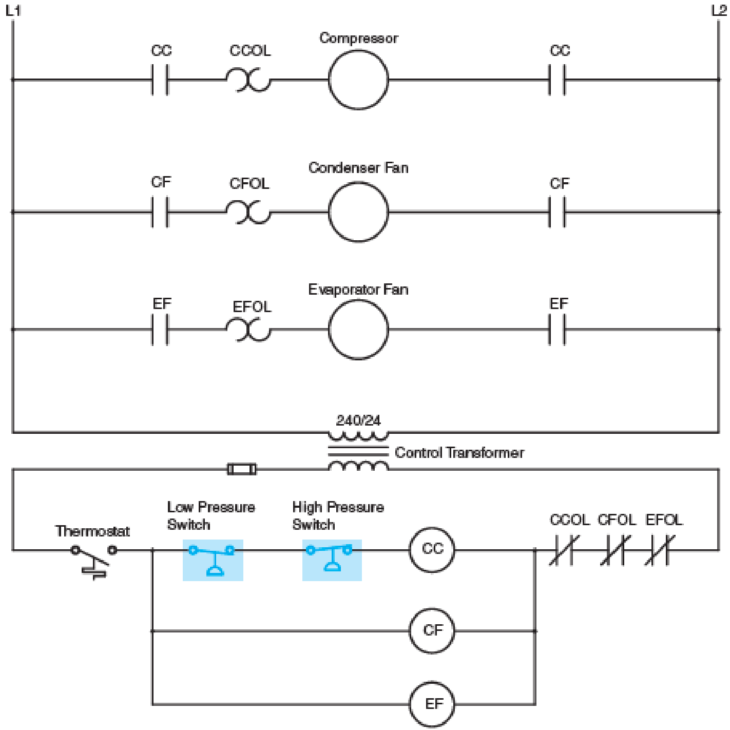
Fig. 10–6 Pressure switches are often used in air-conditioning circuits.
Expert Solution & Answer
Want to see the full answer?
Check out a sample textbook solution
Students have asked these similar questions
Please solve it by explaining the steps. I am trying to prepare for my exam tomorrow, so any tips and tricks to solve similar problems are highly appreciated. Plus, this is a past exam I am using to prepare.
Please solve it by explaining the steps. I am trying to prepare for my exam tomorrow, so any tips and tricks to solve similar problems are highly appreciated. Plus, this is a past exam I am using to prepare.
Please solve it by explaining the steps. I am trying to prepare for my exam tomorrow, so any tips and tricks to solve similar problems are highly appreciated. Plus, this is a past exam I am using to prepare.
Chapter 10 Solutions
Electric Motor Control
Ch. 10 - Describe how pressure switches are connected to...Ch. 10 - What type of pressure switch is generally used to...Ch. 10 - A pressure switch is set to cut in at a pressure...Ch. 10 - A pressure switch is to be installed on a system...Ch. 10 - A pressure switch is to be installed in a circuit...Ch. 10 - Refer to the circuit shown in Figure 105. If the...Ch. 10 - Refer to the circuit shown in Figure 105. Assume...Ch. 10 - Refer to the circuit shown in Figure 106. Assume...Ch. 10 - Refer to the circuit shown in Figure 106. Assume...Ch. 10 - Refer to Figure 106. When the thermostat contact...
Knowledge Booster


Learn more about
Need a deep-dive on the concept behind this application? Look no further. Learn more about this topic, electrical-engineering and related others by exploring similar questions and additional content below.Similar questions
- Please solve it by explaining the steps. I am trying to prepare for my exam tomorrow, so any tips and tricks to solve similar problems are highly appreciated. Plus, this is a past exam I am using to prepare.arrow_forwardPlease solve it by explaining the steps. I am trying to prepare for my exam tomorrow, so any tips and tricks to solve similar problems are highly appreciated. Plus, this is a past exam I am using to prepare.arrow_forwardPlease solve it by explaining the steps. I am trying to prepare for my exam tomorrow, so any tips and tricks to solve similar problems are highly appreciated. Plus, this is a past exam I am using to prepare.arrow_forward
- Please solve it by explaining the steps. I am trying to prepare for my exam tomorrow, so any tips and tricks to solve similar problems are highly appreciated. Plus, this is a past exam I am using to prepare.arrow_forwardPlease solve it by explaining the steps. I am trying to prepare for my exam tomorrow, so any tips and tricks to solve similar problems are highly appreciated. Plus, this is a past exam I am using to prepare.arrow_forwardPlease solve it by explaining the steps. I am trying to prepare for my exam tomorrow, so any tips and tricks to solve similar problems are highly appreciated. Plus, this is a past exam I am using to prepare.arrow_forward
- It is a past exam for practice, please explain what you do so I can be prepared for exam tomorrowarrow_forwardPlease solve it by explaining the steps. I am trying to prepare for my exam tomorrow, so any tips and tricks to solve similar problems are highly appreciated. Plus, this is a past exam I am using to prepare.arrow_forwardPlease solve it by explaining the steps. I am trying to prepare for my exam tomorrow, so any tips and tricks to solve similar problems are highly appreciated. Plus, this is a past exam I am using to prepare.arrow_forward
- Please solve it by explaining the steps. I am trying to prepare for my exam tomorrow, so any tips and tricks to solve similar problems are highly appreciated. Plus, this is a past exam I am using to prepare.arrow_forwardIf C is the circle |z|=4 evaluate ff(z)dz for each of the following functions using residue. Z (a)f(z) = z²-1 Z+1 1 (b)f(z) = = (c)f(z) = z²(z+2) z(z-2)³ z² 1 1 (d) f(z) = = (e) f(z) = (f) f(z) = (z²+3z+2)² z²+z+1 z(z²+6z+4)arrow_forward5. Answer the following questions. Take help from ChatGPT to answer these questions (if you need). Write the answers briefly using your own words with no more than two sentences, and check whether ChatGPT is giving you the appropriate answers in the context of our class. a) What is the Bode plot? What kind of input do we consider for the frequency-response- based method? b) What is the advantage of design using the frequency-response method? c) Define gain margin, phase margin, gain crossover frequency, and phase crossover frequency.arrow_forward
arrow_back_ios
SEE MORE QUESTIONS
arrow_forward_ios
Recommended textbooks for you
 Electricity for Refrigeration, Heating, and Air C...Mechanical EngineeringISBN:9781337399128Author:Russell E. SmithPublisher:Cengage Learning
Electricity for Refrigeration, Heating, and Air C...
Mechanical Engineering
ISBN:9781337399128
Author:Russell E. Smith
Publisher:Cengage Learning
Pressure Sensors with Display; Author: Balluff Worldwide;https://www.youtube.com/watch?v=HqAV2xjCLxE;License: Standard Youtube License