
ELECTRICAL WIRING:RESIDENT.-TEXT (PB)
19th Edition
ISBN: 9781337116213
Author: MULLIN
Publisher: CENGAGE L
expand_more
expand_more
format_list_bulleted
Concept explainers
Videos
Textbook Question
Chapter 10, Problem 10R
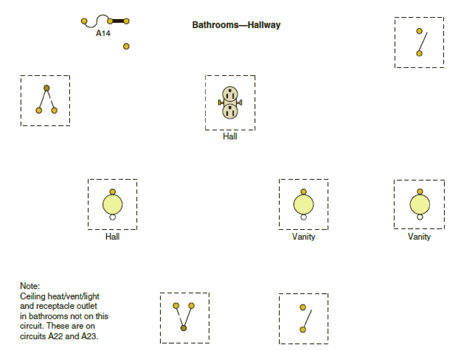
The following is a layout of a lighting circuit for the bathroom and hallway. Using the cable layout shown in Figure 10-1, make a complete wiring diagram of this circuit. Use colored pencils or pens.
Expert Solution & Answer

Trending nowThis is a popular solution!

Students have asked these similar questions
Choose the correct answer to the following questions:
1- What is the total power radiated in Watts for the power density W =
a) 4π²
b) 8m²/3
2- Fresnel zone is also called as
sine
W/m²?
3r²
c) 4π²/3
d) 2π²/3
a) Near Field b) Far Field
c) Electrostatic Field
d) Reactive Field
3- The far-field distance at 900 MHz, if the maximum antenna dimension is 0.75 m is....
a) 3.375 m
b) 3.5m
c) 3.375 cm
d) none
4- The antenna gain is
on input power to antenna and
on power due to ohmic losses.
c) Independent, dependent d)
a) Independent, independent b) Dependent, independent
Dependent, dependent
5- If beam width of the antenna increases, then directivity.
a) Decreases b) Increases c) Remains unchanged d) Depends on type of antenna
please solve this and clarify each step. thanks
The input reactance of 1/2 dipole with radius of 1/30 is given as shown in figure below,
Assuming the wire of dipole is conductor 5.6*107
S/m, determine at f=1 GHz the
a- Loss resistance, b- Radiation efficiency
c- Reflection efficiency when the antenna is
connected to T.L shown in the figure.
Rr
Ro= 50 2
Avg/4
RL
-j100
[In(l/a) 1.5]
tan(ẞ1)
Chapter 10 Solutions
ELECTRICAL WIRING:RESIDENT.-TEXT (PB)
Ch. 10 - Prob. 1RCh. 10 - There is a 3-way switch in the bedroom hallway...Ch. 10 - What wattage was used for each vanity luminaire to...Ch. 10 - What is the current draw for the answer given in...Ch. 10 - Exposed non-current-carrying metallic parts of...Ch. 10 - What color are the faceplates in the bathrooms?...Ch. 10 - Prob. 7RCh. 10 - a. The NEC in Section _______________ requires...Ch. 10 - Hanging luminaires must be kept at least...Ch. 10 - The following is a layout of a lighting circuit...
Knowledge Booster


Learn more about
Need a deep-dive on the concept behind this application? Look no further. Learn more about this topic, electrical-engineering and related others by exploring similar questions and additional content below.Similar questions
- Find Zeq here. i already had one solution written to me but it's wrong. my main question is. i know that i do the parallel connection first so 2x2 / 2+2 = 1ohm but what i'm asking is since it's an open terminal is R3,2(parallel resistors) in series to R1? or should i first do R3,2 // to ZL and then add R1 in series? PLEASE READ THIS. and solve properly. EXPLAIN WHAT I ASKED PROPERLY. UPVOTE WILL BE GIVEN.arrow_forwardThe E-field pattern of an antenna, independent of o, varies as follows: E = 0 7100 0° ≤0≤45° 45° < 0 ≤ 90° 90° < 0 ≤ 180° (a) What is the directivity of this antenna? (b) What is the radiation resistance of the antenna at 200 m from it if the field is equal to 10 V/m (rms) for 0 = 0° at that distance and the terminal current is 5 A (rms)?arrow_forwardFind Zeq here. i already had one solution written to me but it's wrong. my main question is. i know that i do the parallel connection first so 2x2 / 2+2 = 1ohm but what i'm asking is since it's an open terminal is R3,2(parallel resistors) in series to R1? or should i first do R3,2 // to ZL and then add R1 in series? PLEASE READ THIS. and solve properly. EXPLAIN WHAT I ASKED PROPERLY. UPVOTE WILL BE GIVEN.arrow_forward
- Find Zeq here, ignore the semi circle in the wiring i'm just bad at drawing circuits. ZL=JWL write Zeq in terms of JW and give me the final equation. (basically check the parallel and series combinations and give me the final answer.)Will upvote correct answer. Thanks!arrow_forwardFill in the chart and answer questions Answer problems 10, 11, and 12 using the following information:An addition is being planned to a school building. You have been asked to determine theload that will be added to the panelboard that will serve this addition.The addition will be a building 80 ft 3 50 ft. It will consist of four classrooms, every40 ft 3 20 ft and a corridor that is 10-ft wide The following loads will be installed:Each classroom:12 fluorescent luminaires, 2 ft 3 4 ft @ 85 VA each20 duplex receptaclesAC unit, 208-volt, 1-phase @ 5000 VACorridor:5 fluorescent luminaires, 1 ft 3 8 ft @ 85 VA each8 duplex receptaclesExterior:4 wall-mounted luminaires @ 125 VA each4 duplex receptacles 10. The calculated load is__________ VA.11. The connected load is__________ VA.12. The neutral load is_____________ VA.arrow_forwardA 1200-ampere service was installed, consisting of three sets of 600 kcmil THHN/THWN copper conductors per phase. The electrical contractor was careful to cut theconductors the same length. When the utility crew made up the connections at theservice heads, they cut the conductors to different lengths to make their connectionssimpler. The actual lengths of the service-entrance conductors in a given phase ended up being20 ft (6.1 m), 22 ft (6.7 m), and 24 ft (7.3 m). The maximum ampacity of a 600-kcmilTHHN/THWN copper conductor is 420 amperes using the 75°C column of Table310.16. This is more than adequate for the calculated 1200 amperes when three conductors are run in parallel. Determine how the load of 1200 amperes would divide in each of the three paralleledconductors in a phase.arrow_forward
- Determine the conductor sizes for a feeder to a panelboard. It is a 120/240-volt,single-phase system. The OCPD has a rating of 100 amperes. The calculated load is15,600 VA. All the loads are 120 volts.arrow_forwardCalculate the neutral current in a 120/240-volt, single-phase system when the current inphase A is 20 amperes and the current in phase B is 40 amperes. The load is resistive. Calculate the neutral current in a 208Y/120-volt, 3-phase, 4-wire system when thecurrent in phase A is 0, in phase B is 40, and in phase C is 60 amperes. The load isresistivearrow_forwardCalculate the neutral current in a 208Y/120-volt, 3-phase, 4-wire system when the current in phase A is 20, in phase B is 40, and in phase C is 60 amperes. The load is resistive.arrow_forward
arrow_back_ios
SEE MORE QUESTIONS
arrow_forward_ios
Recommended textbooks for you
 EBK ELECTRICAL WIRING RESIDENTIALElectrical EngineeringISBN:9781337516549Author:SimmonsPublisher:CENGAGE LEARNING - CONSIGNMENT
 Electricity for Refrigeration, Heating, and Air C...Mechanical EngineeringISBN:9781337399128Author:Russell E. SmithPublisher:Cengage Learning
EBK ELECTRICAL WIRING RESIDENTIAL
Electrical Engineering
ISBN:9781337516549
Author:Simmons
Publisher:CENGAGE LEARNING - CONSIGNMENT
Electricity for Refrigeration, Heating, and Air C...
Mechanical Engineering
ISBN:9781337399128
Author:Russell E. Smith
Publisher:Cengage Learning
What is an electric furnace and how does it work?; Author: Fire & Ice Heating and Air Conditioning Inc;https://www.youtube.com/watch?v=wjAWecPGi0M;License: Standard Youtube License